Arty Piston-Broke - Artisan
  • Home
  • Portfolio
  • Enquiries
  • Blog
  • For Sale
  • Steampunk Medals for Sale
  • Events and Exhibitions

The 'Thinktank'

22/6/2015

1 Comment

 
Picture
Since I got drawn into the heady realms of Steampunk, I have seen many examples of beautifully made ‘brains in jars’ over recent years and, I had often thought that I would also make one myself one day. Well, I have finally got round to doing just that, It took me a month to complete but things didn’t stop with just the brain in a jar!

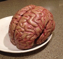
As with all mad scientists’ inventions, it all started off with the search for a brain! I did think about modelling one myself, but managed to source a vinyl anatomy model which was actual size and fitted perfectly into my 170mm diameter glass container. Being hollow, it was also very lightweight. Once assembled, I painted it with acrylics and inks and gave it a silky sheen clear varnished finish. Brass banding and inserts were then applied to act as the connection points for the wires later.

Picture
Picture
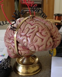
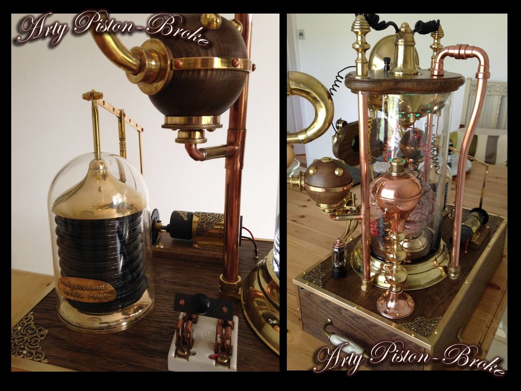
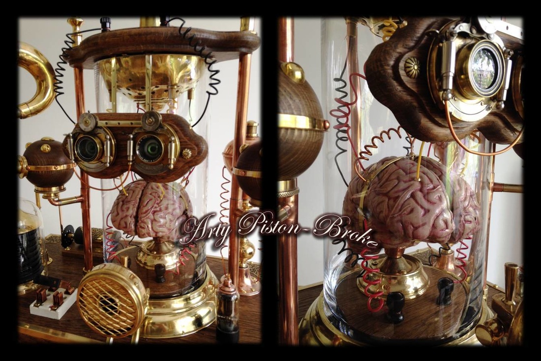
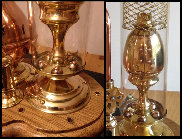
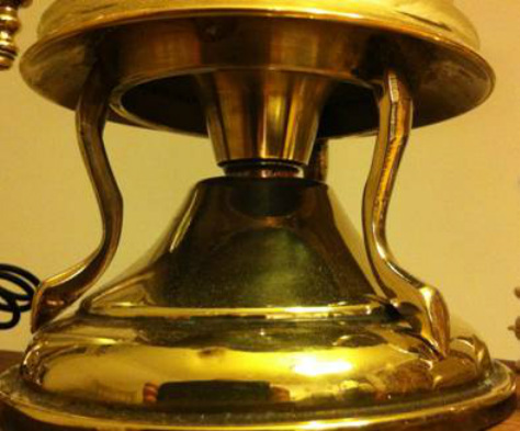
The brain had to be mounted/supported in the container somehow, so I used part of an old candlestick base and a domed-out 22mm pipe end soldered at an angle for the brain stem to fit into. I then had to make an oak base to form a platform for the brain assembly. This took some time as it had to be shaped to fit flat in a container that did not have a flat base, such is the nature of glass! Once given a couple of applications of antique wood stain and waxed, two vintage Bakelite terminals were installed as connection points for wires connecting to the brain.

Picture
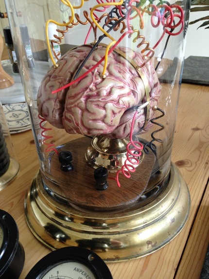
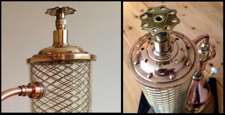
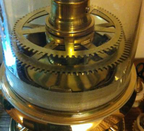
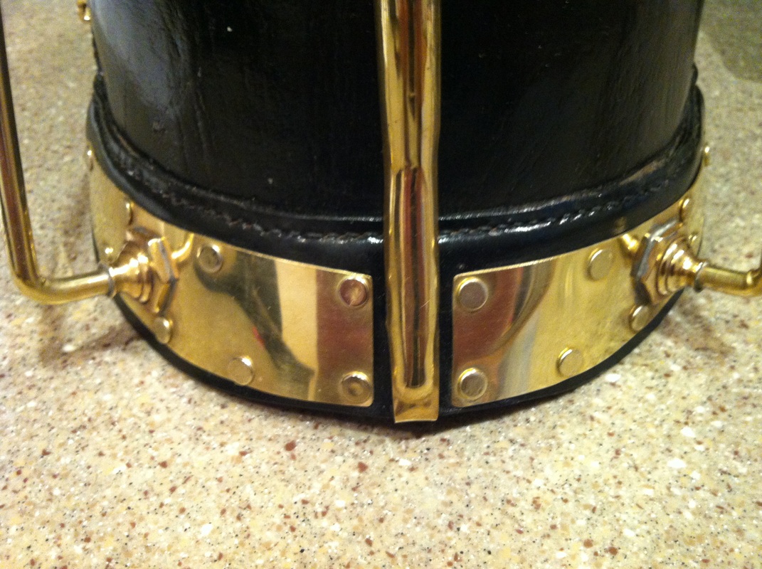
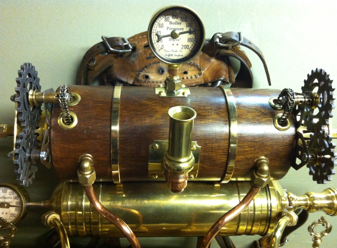
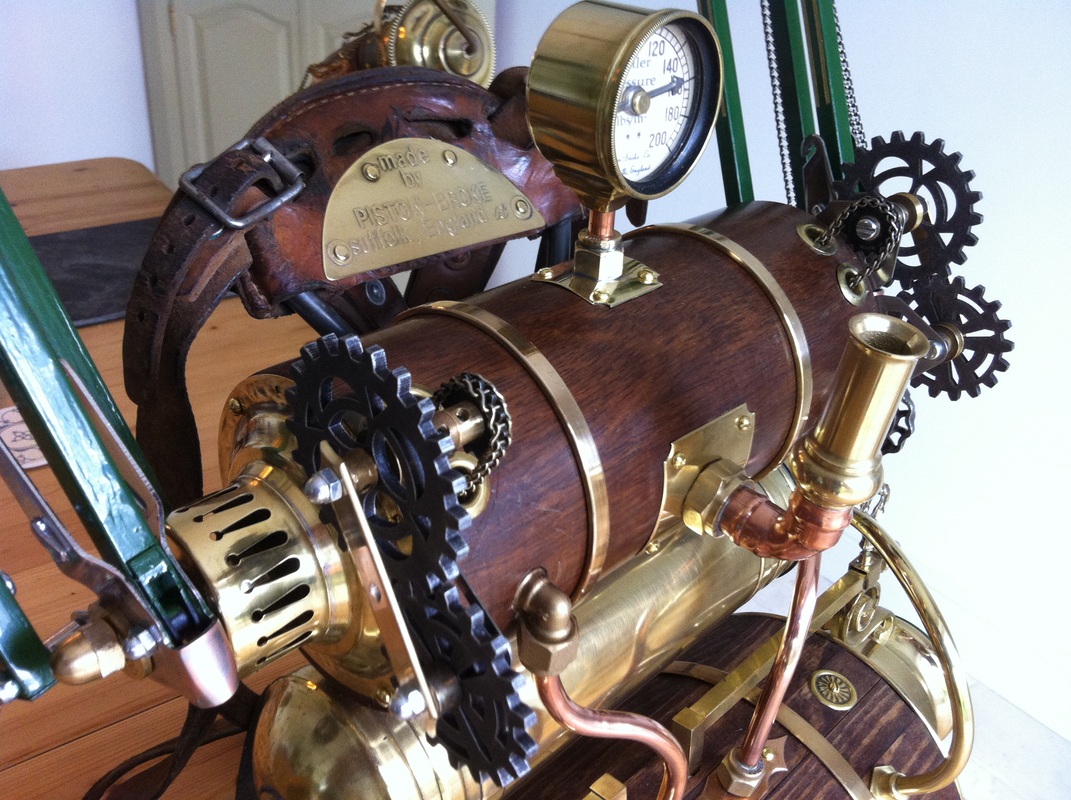
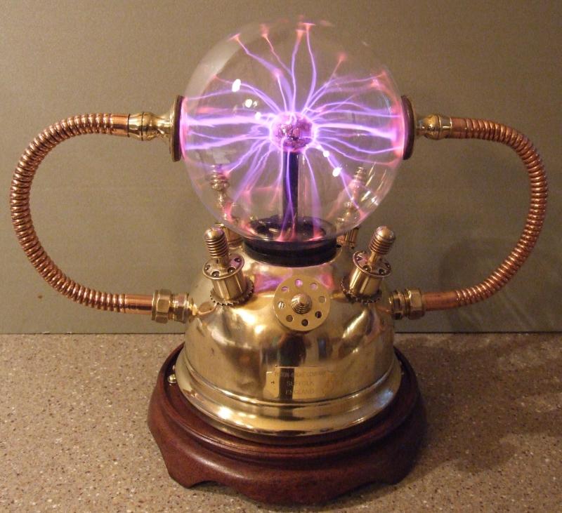
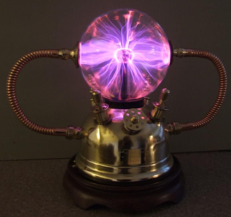
I had previously sourced an old brass planter which had a 170mm aperture, (hence purchasing a glass container to fit!) from which  I removed the topmost section to use as a flange support for the glass container. The oak base raised the brain enough to be level with the top of the brass flange. Inside the top of the container I needed to have some sort of arrangement to connect all of the wires from the brain to. I had an old Tilley ‘Guardsman’ lamp in the workshop which fitted the bill well. It has four terminals where the original frame was mounted which could be used for the wires. I removed the top section to a diameter of 163mm so that it fitted snugly into the top of the container. An old brass horse harness disc was riveted on to cover the hole in the centre and two more inserts were added for the 5th and 6th wires coming off the brain. Numerous holes were then drilled into the dome which would allow light from a mains powered sequencing rope light to illuminate the interior of the container. Four thin tabs were riveted to the edge to allow it to be secured to the wooden lid. The matching oak lid was cut to shape and its edges routed and shaped on both top and bottom faces. Three 15mm holes were drilled to receive the copper support pipes at either side and the pipe to route the lights into the dome. The same staining and waxing was applied to match the base of the brain.

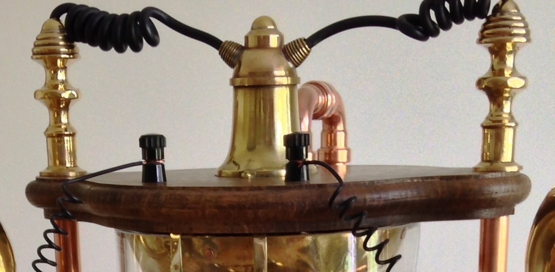
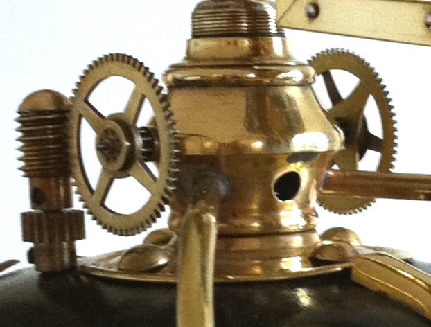
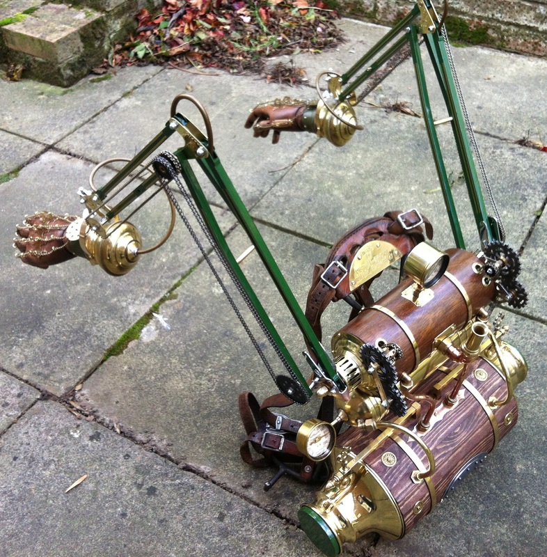
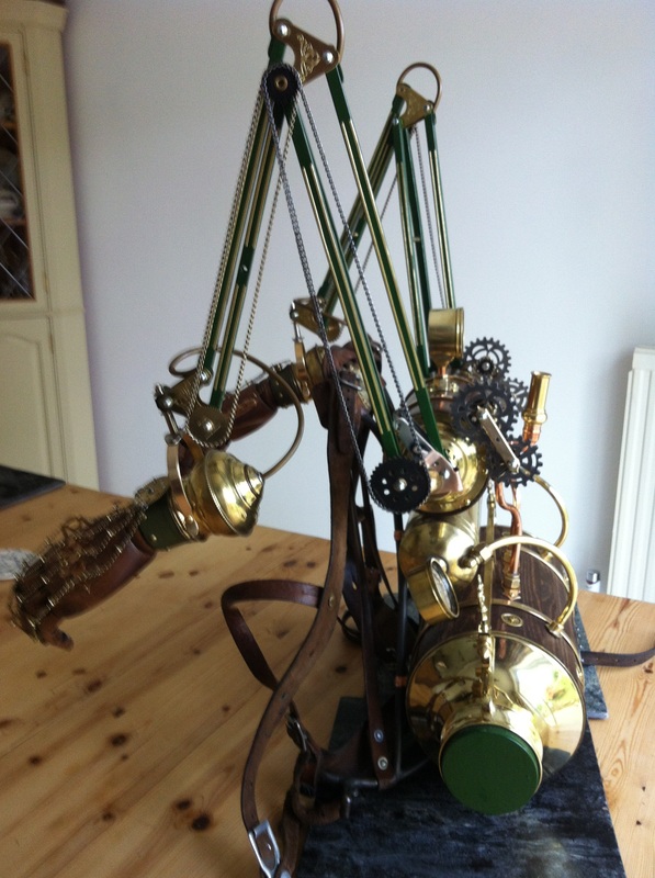
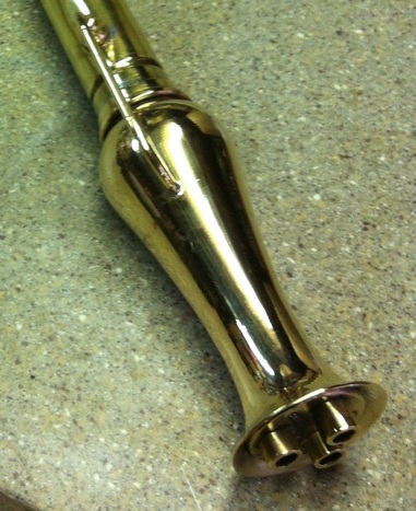
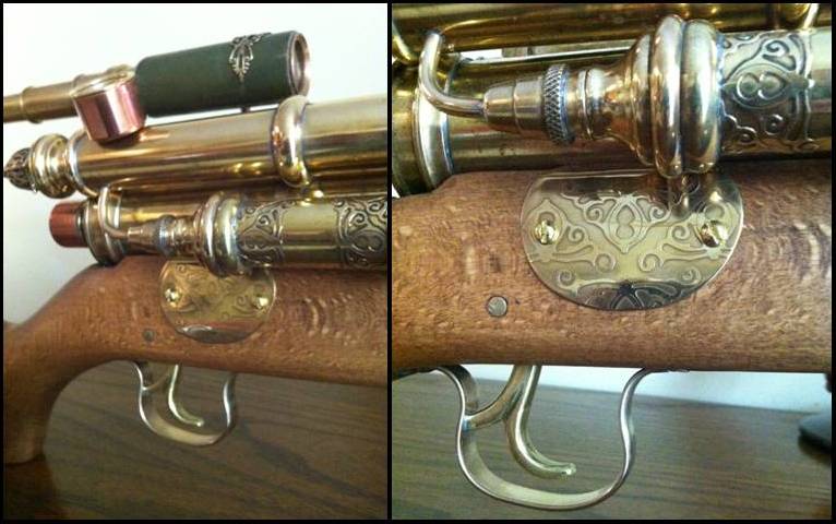
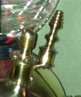
The two copper support columns were cut to lengths to fit into push-fit plumbing fittings screwed into the top of the base unit and for the fitting of brass finials on top. Intersections were added using 15mm to 10mm reducers to act as supports for the audio trumpets. The finials of the supports were made from a pair of candle sticks cut to length and fitted with a brass dome cap hammered from 1.5mm brass sheet. Two more Bakelite terminals were fitted to the front of the lid which will connect the brain to the optical device later. Additional details such as the central connector for wiring to the finials were fitted to the lid including the copper pipe ducting for the lights inside the container.
Picture
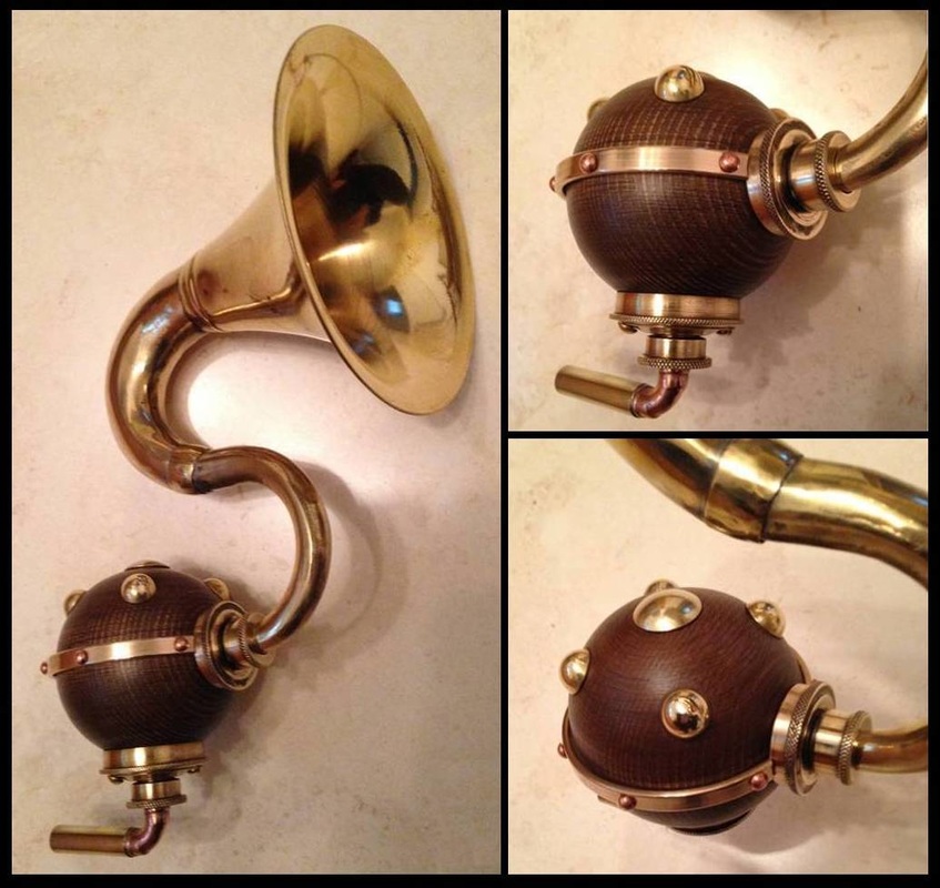
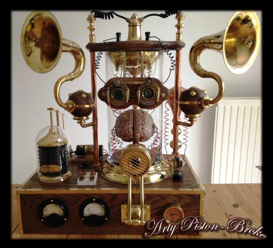
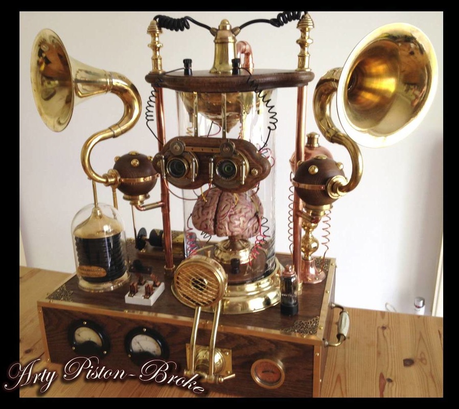
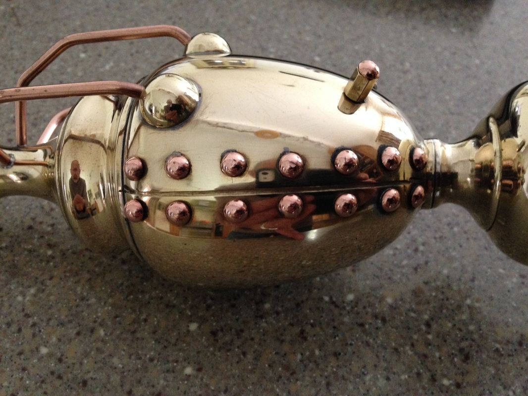
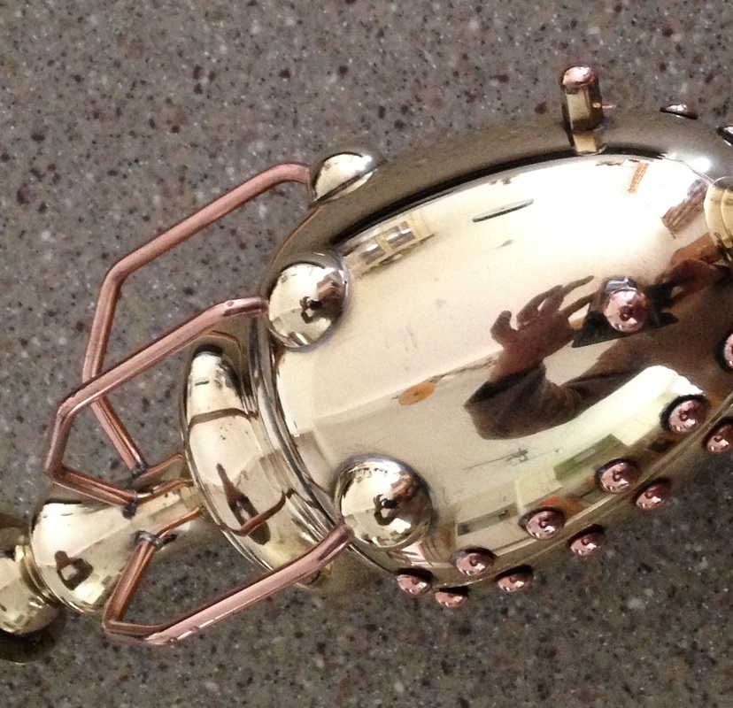
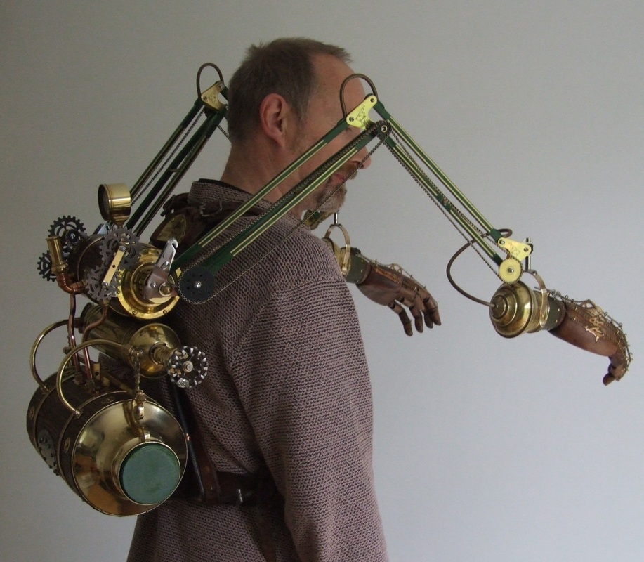
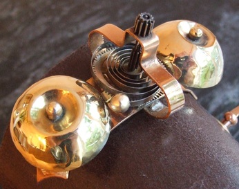
For the brain to operate as a disembodied living entity, I decided that it would need to have sensory input/output. It would need to see, hear and vocalise through artificial means. Hearing, I decided would be via two audio horns which would funnel sound to artificial eardrum membranes transmitting the vibrations as electrical signals to the brain. These were made from two brass car horns with the rubber bulbs removed and a section of the tubing reversed to create an ‘S’ shape. These were then mounted onto 3” wooden balls with brass support brackets. The brass domed studs were made with sheet brass and a doming block, and fitted along with a decorative brass banding secured by copper rivets. The sub-assemblies were then fixed to the copper uprights using the 15mm – 10mm reducing tees.
Picture
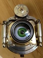
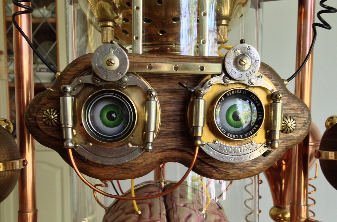
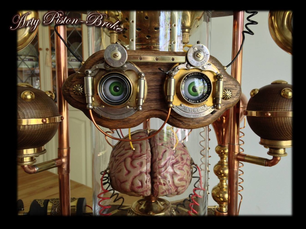
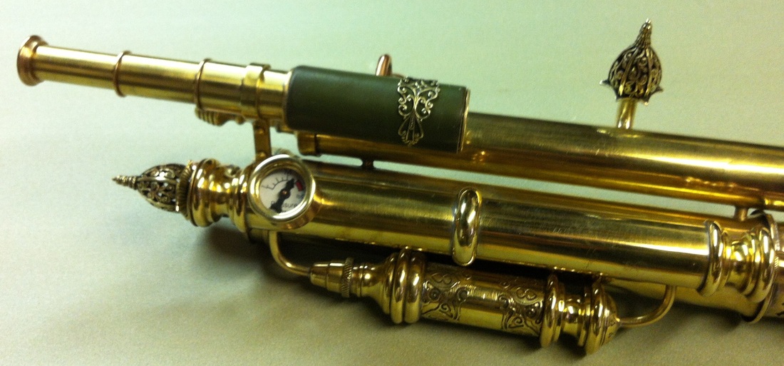
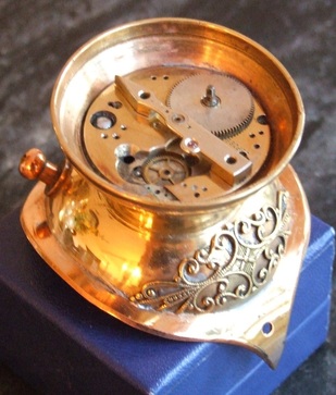
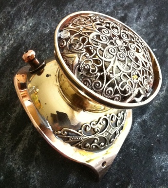
For the optical input, I had originally envisaged a pair of goggles. However, I managed to source a pair of old  plate camera symmetrical shutter and lens assemblies which fitted the bill perfectly, and saved me from making a special pair of goggles! The lens assemblies were mounted at the front of the container on a wooden backing plate, secured to the lid with 1/4” brass hangers. I also took the lenses apart and inserted a false eyeball for additional effect.
Picture
Picture
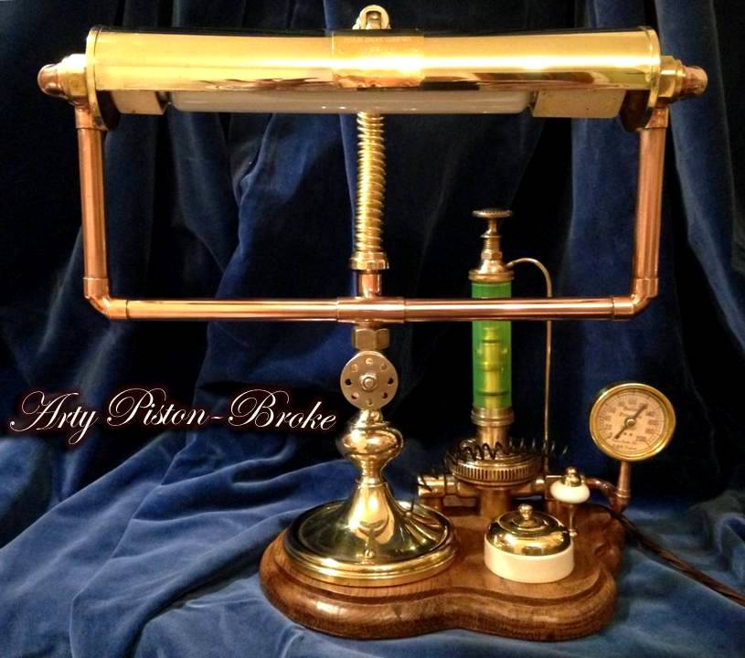
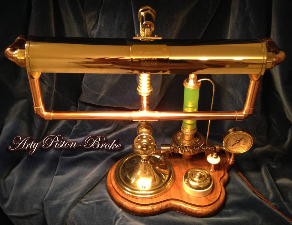
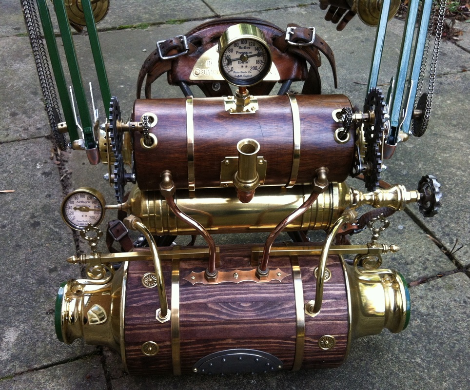
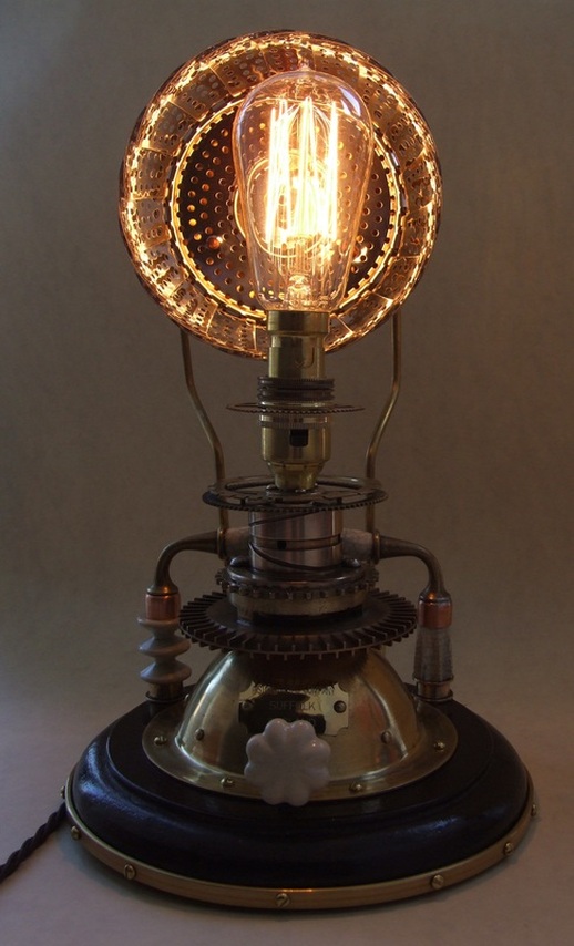
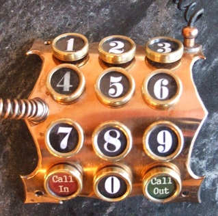
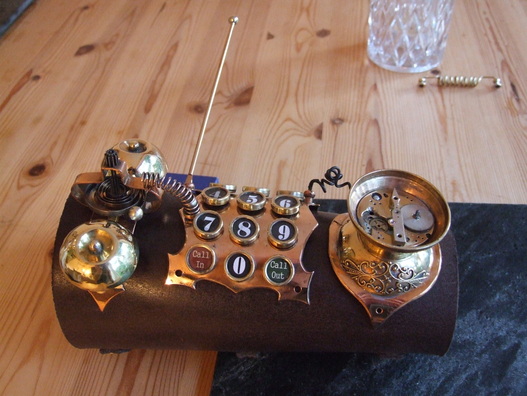
Speech was handled by using the microphone section from an old candlestick telephone and the twin arm from an old bankers desk lamp, combined to resemble an old speaker unit. An additional grille and flange ring were added to the face of the assembly. (A simple speaker circuit was installed, which generates sound operated by a small switch positioned on the side of the base unit). When the circuit is activated, a colour-changing LED also lights up beneath the old radio valve set into the top of the base unit. 

The base unit was constructed from 18mm x 120mm pine onto which I applied an oak veneer, then stained and waxed to match the other oak parts. The box is edged in brass with decorative brass filigree corners. Two holes were cut into the front panel to accommodate a pair of old Bakelite meters (amperes and voltage). Ceramic and brass carrying handles were also added as this is going to be quite a heavy piece! 

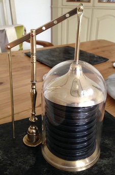
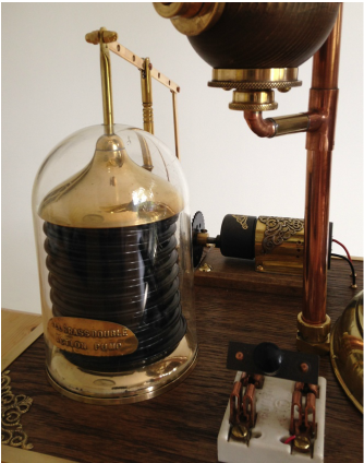
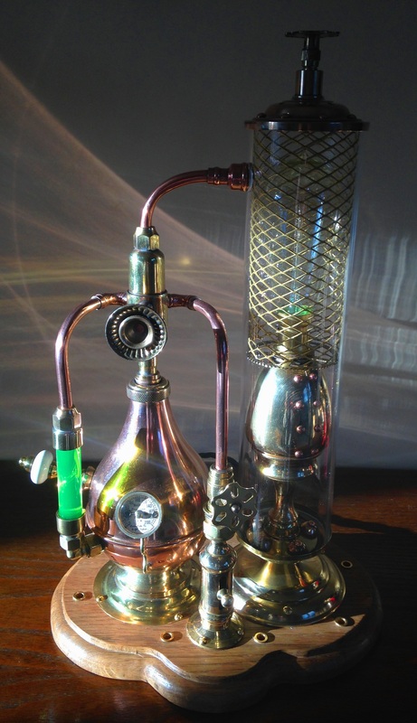
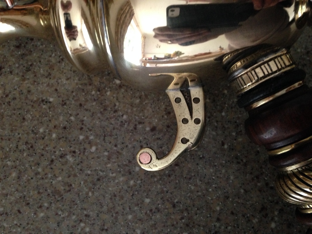
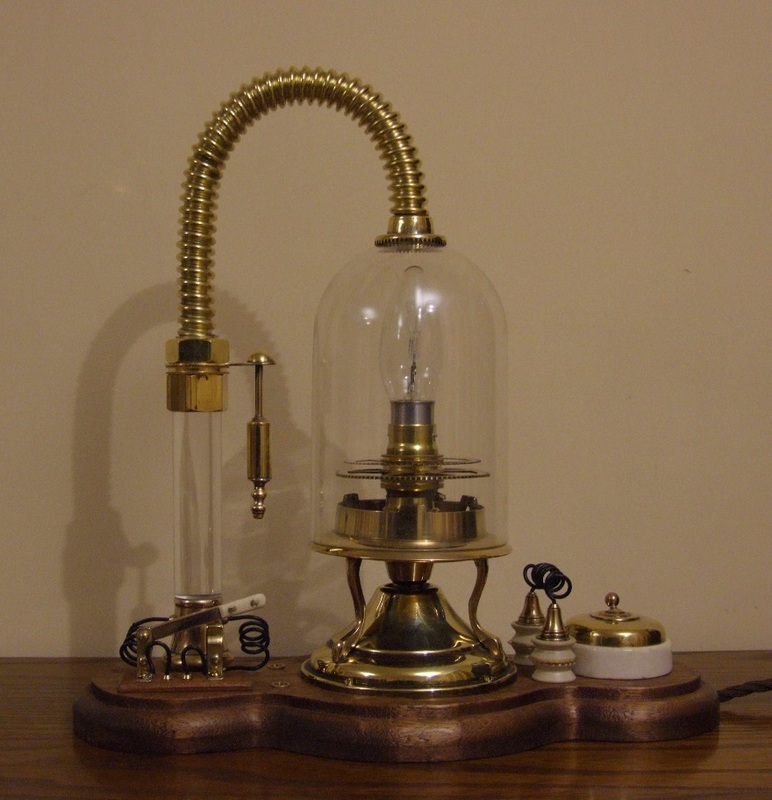
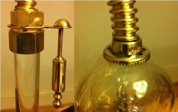
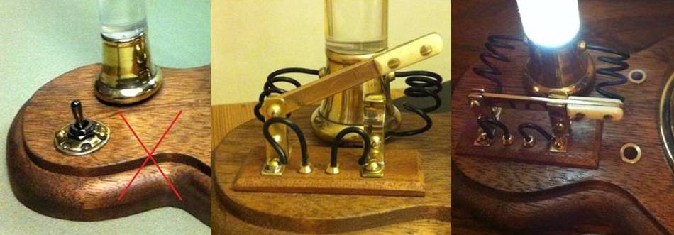
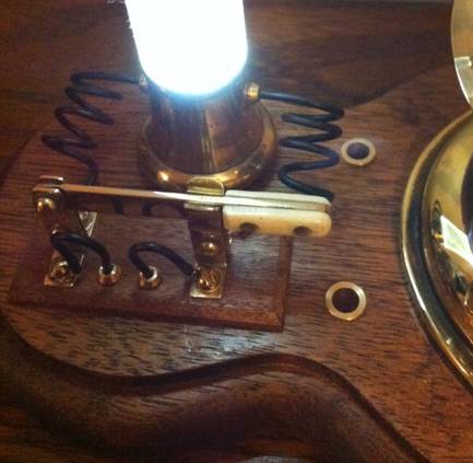
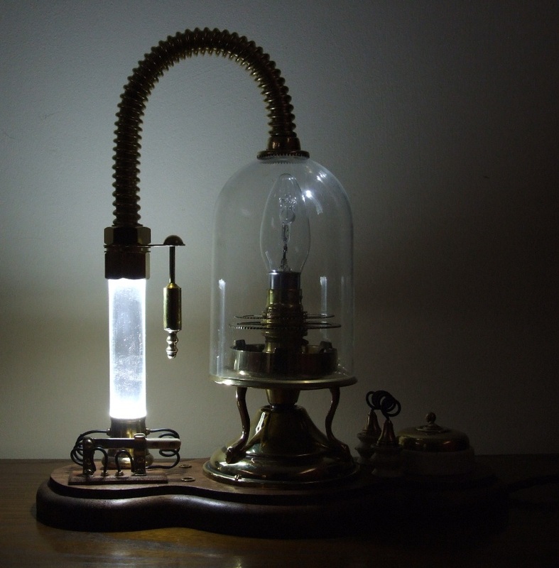
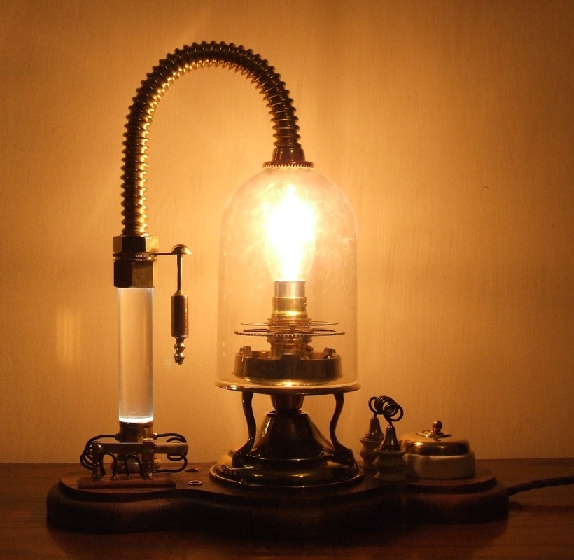
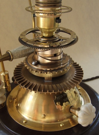
As we all know, brains cannot function without an oxygen supply, so I created an auxiliary oxygen pumping unit. I started with a 9v DC stepped gear motor with a high torque ratio. I painted the red plastic cowl a grey iron colour, made and fitted a  decorative brass housing and mounted in onto a small wooden base. The rocker bar is raised and lowered by the pushrod run on a stainless steel bearing riveted to a Meccano chain wheel. The central pillar is made from a candlestick and a length of 8mm diameter stock brass rod to which I added a turned decoration. The compression unit is made using two brass candlestick bases, a 110mm length of internally-sprung air ducting hose and an acrylic display dome. The motor is switched on and off using a vintage ceramic and copper knife switch connected to a 9v battery power supply.
Picture
Picture
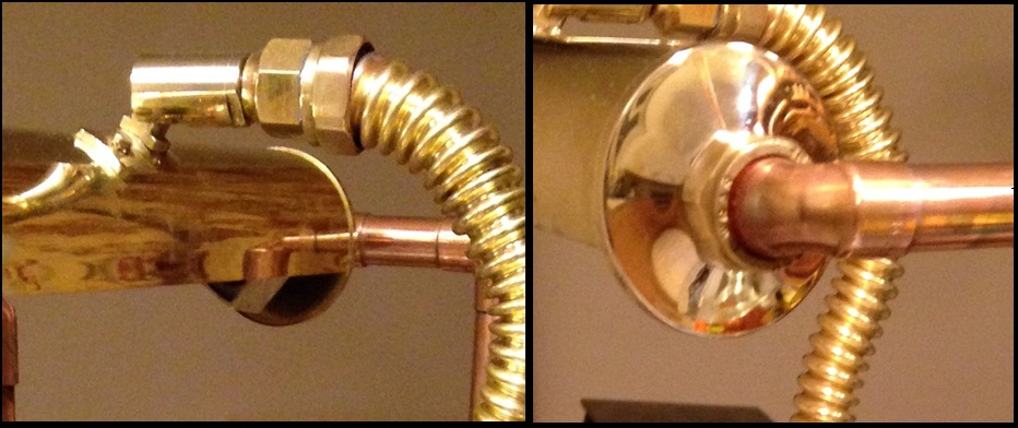
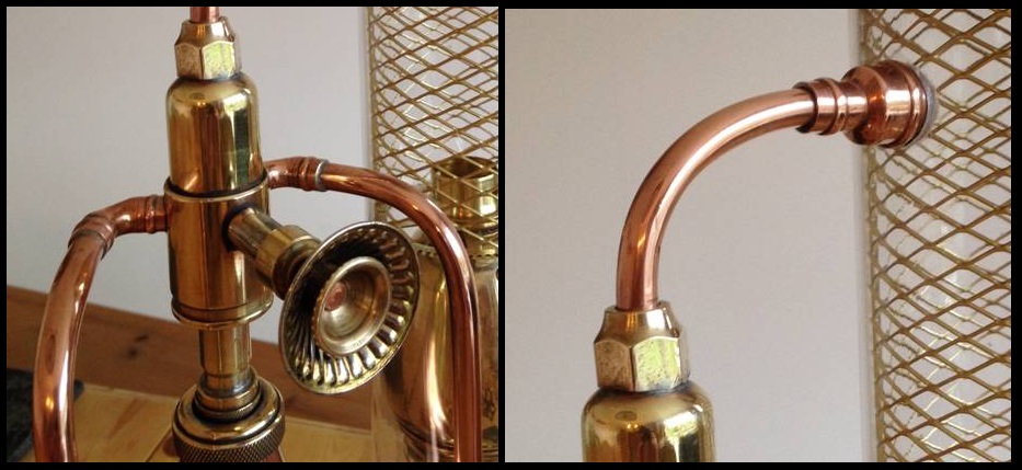
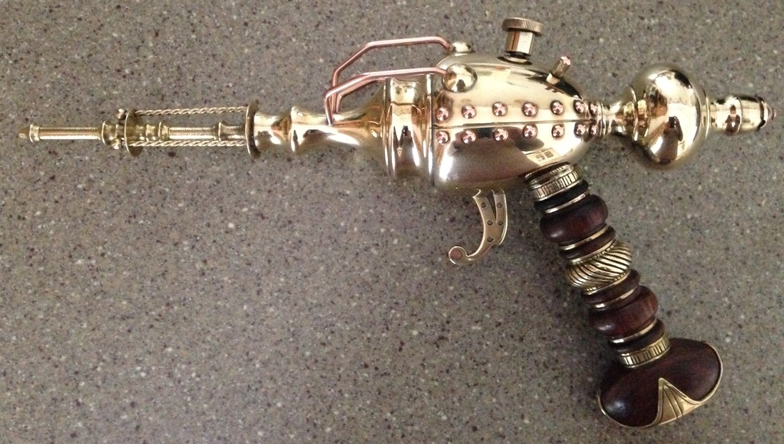
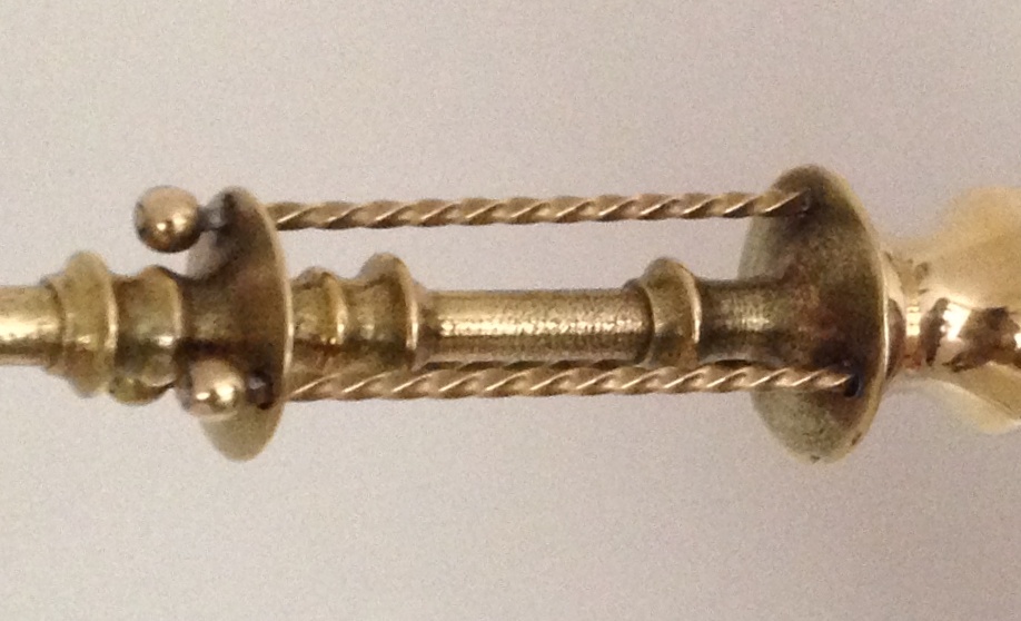
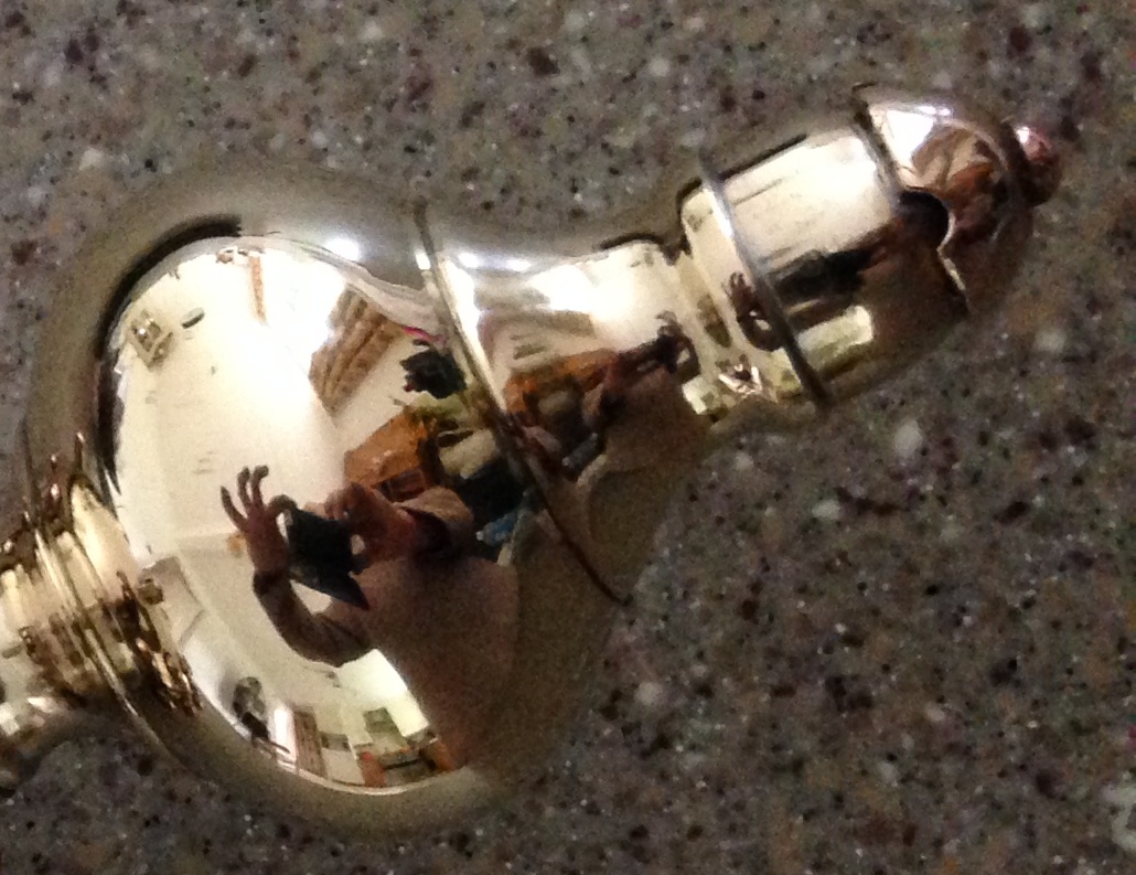
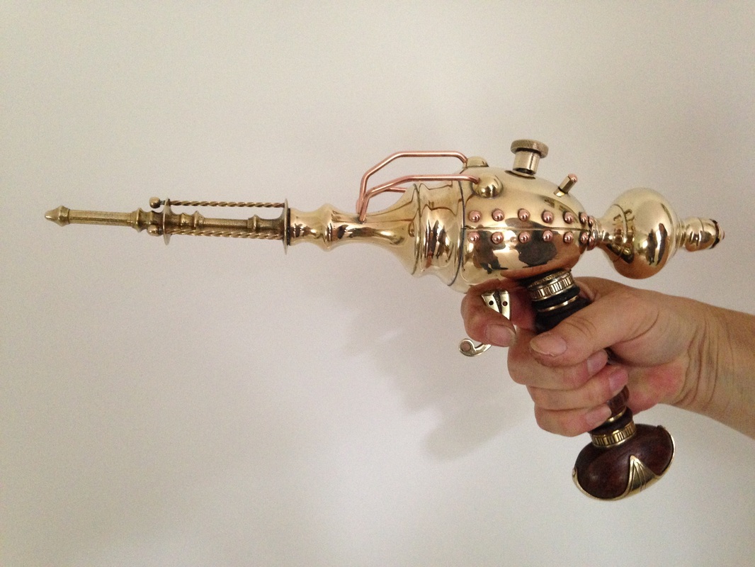
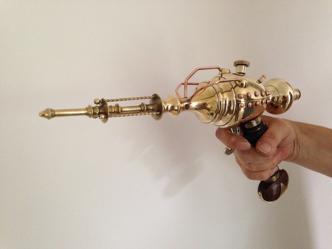
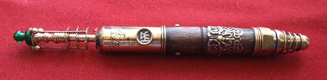
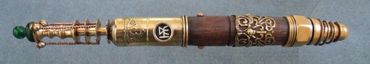
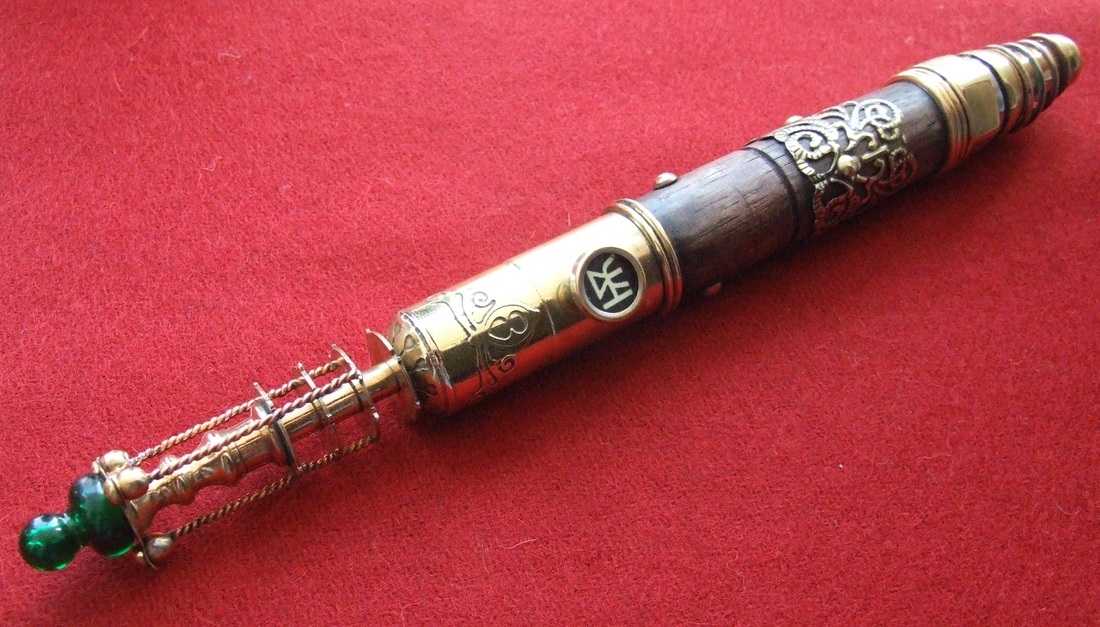
Finally, a copper and brass electrical conductor was made from parts of a candlestick and a small copper jug. I then added a brass finial and two lengths of coiled copper wire.
1 Comment

The 'Bigfoot' reading lamp

22/5/2015

0 Comments

 
Picture
The Bigfoot Reading Lamp – A commissioned piece

This piece was commissioned and completed in January 2015 and was quite a simple piece to construct. The basis of this build was an old wall-mounted down-lighter with most of the bracket and 12mm gooseneck tubing removed, I then fitted two brass connecting nuts to accept the flexible brass gas-pipe used as a replacement goose neck. The main stem for the lamp itself was made using parts from a couple of old desk lamps, A 15mm wheel valve and lengths of 15mm copper pipe and fittings.

Picture
The copper pipe was cut to length and soldered to form a supporting frame for the lamp shade section. 15mm brass nuts were soldered to each end of the shade to receive the copper pipe framework. Once all the upright and frame was in-place the wiring could be fed through the brass flexible hose and the upright support and into the base. The internals of the wheel valve were adjusted in order that the electrical supply was not damaged if the wheel was tightened fully.
Picture
The sight glass sub assembly started life as a gas regulator from oxy-acetylene welding equipment and part of a domestic garden hose end. The body was cut to size and tooled to receive the additional fittings and base connections. The sight ‘glass’ is 28mm acrylic tube capped with a light fitting into which I soldered a brass tapered ring to act as a tight-fitting stopper. This is then topped with a drawer pull for the valve wheel. The 1/8” brass tubing is soldered into the hole left by removal of the earth wire connector. All joints were sealed before adding the luminescent green fluid.
A ‘Piston-Broke’ pressure gauge made from a 50mm brass female connector and, was soldered to 8mm copper pipe work to complete this assembly.

Picture
Added to these assemblies are the vintage brass and ceramic light switch and the insulator pole (made from a bathroom light-pull) and coiled wiring. Then all were fixed to the custom-shaped and chamfered oak base. The base was routed out underneath to accommodate the wiring, stained and waxed to a dark oak finish.
Picture
Picture
Picture
Picture
Picture
0 Comments

Aether Boiler Desk Lamp

5/1/2015

1 Comment

 
Picture
This desk lamp build utilises many salvaged and re-purposed components from various objects such as a copper jug, candle stick and lamp parts, plumbing components as well as some custom made parts. The Boiler Section.

This started its life as an ornamental copper jug which I de-constructed to remove the handle, pouring spout and copper base. I replaced the base with a two-part brass base, wider at the foot than the original and with a flat flange to allow it to be fixed to the wooden base. The small pressure gauge is made from the cup section of a light bulb holder. The dial is made by cutting a thin disc of 28mm diameter dowel and one of my printed adhesive dial plates. The pointer is a shop-bought one from a card-craft supplier. This is held in place by a small brass rivet. The glass dome is a watch crystal held in place by the screw-threaded lampshade ring. This, and the small brass pipe had to be soldered into place before adding the internals.

Picture
The glass sight gauge uses an 8mm brass elbow fitting at the bottom, soldered into a 16mm hole drilled into the side of the copper body. The glass phial is filled with a water-based luminescent coolant. This is capped at the top and bottom by plastic-lined brass dimmer switch covers. A second 8mm cone nut is used as a guide for the copper pipe leading to the three-way brass fitting on top of the boiler. The brass and ceramic ‘tap’ on the side of the boiler is made using a light-pull and a 15mm brass end cap. The wheel valve section is made from an inverted portion of a candlestick (with ejector) and an in-line valve from an old Tilley lamp. The wheel itself I fashioned from 1.5mm brass sheet.
Picture
The three-way brass top section of the boiler is taken from an old Tilley lamp. Two of the original steel tubes have been replaced with 8mm copper elbow joints to accept the copper pipes. A double brass flared ‘horn’ was fixed to the third tube. This was made from riveting together the mouthpiece of an old post horn and the horn from a small gramophone ornament. Another 8mm brass cone nut is soldered to the top to accept the copper pipe connecting it to the lamp section.
Picture
The Lamp Section.

The base of the lamp is made from two parts of an old brass candlestick lamp and a 70mm diameter brass cup from an old chandelier. I cut out five bronze discs and hammered them into cup shapes using a doming block and then riveted these to one of the candlestick bases for decoration. The acrylic tube is 70mm diameter and slots very nicely into the brass cup from the chandelier.
Picture
The upper ‘bulb’ section is made from the two-part cast brass lamp stand. I had to drill out a 28mm diameter hole to receive the light bulb holder and I also cut a false seam and added some copper rivets. The light bulb holder is fitted with a large gear from a clock which splits the light tube in two at the half-way point. A section of pressed brass mesh was added inside the top half of the acrylic tube to alleviate some of the heat from the light bulb. This also adds a very interesting pattern to any lit surfaces. This section is then capped-off with another cast brass candlestick base into which I drilled holes for heat escape and added a working air lock valve topped with a re-shaped Mecanno wheel and added decorative copper rivets.
Picture
All three sections are then mounted on to a solid oak base cut to fit the shape of the three parts. This was stained and waxed to give the wood a medium ‘Georgian oak’ colour. Brass inserts were also added for decoration. Even in daylight it really makes an impact with reflected and diffused light.
Picture
1 Comment

The Piston-Broke Temporal Disruptor

9/9/2014

2 Comments

 
Picture
This project started its life as one of a pair of hollow-cast brass lamp stands. The stands were made up of four sections. I took apart the lamp and discarded the base section (for now!) and removed the light bulb holder.

After all the lacquer was removed with wire wool, the next step was to construct each section in order.

Firstly, I cut a groove with a saw along each side of the main ‘bulb’ section. Once happy that they looked like the component was made in two parts, I marked and drilled 14 holes each side along the lines.The next step was to solder the tapered part of the body (muzzle section) to the bulb part. I could then solder-in 28 x 1/8” x 3/8” copper dome-headed rivets. This gave the appearance of the section being two-part and riveted together.
Picture
Stage two was to construct the front-end of the weapon. The main component is taken from an old wall-mounted brass candle sconce. The two ends were removed and the tip shaped into a conical terminal. 25mm holes were then drilled in the two flared sections ready to accommodate the twisted brass wires. The twisted wires were made by simply taking some square section brass rod, gripping one end in a vice and the other end into an electric drill.

Keeping the tension in the rod taught, short bursts of the drill will twist the rod. Cut this into lengths required and solder-on a brass ball terminal on one end of each rod. These were then positioned and soldered into place along the ‘barrel’ between the flared sections. Once completed, this part was then soldered on to the main body assembly.
Picture
Piping and pipe terminal domes. Three evenly spaced 1/8” holes were drilled into the barrel section. These will take the forward end of the 1/8” copper pipes. Three brass domes were made from 1mm thick brass sheet, cut into discs, annealed and domed by hand in a doming block. 1/8” holes were then drilled to receive the other end of the copper pipes. Once soldered into place, the pipe-work was complete. Lastly, two holes were drilled to accommodate two small brass hex nuts (the type used as spacers in computers) which were capped with a copper rivet to compliment the ones along the flanks of the weapon.
Picture
The rearward bulb was then soldered into place, which, in turn was capped with a brass dome and a secondary bronze dome with cut-outs for decoration.

Picture
My initial thoughts for the grip were to cut and shape a wooden grip and inset it with upholstered leather or bone. However, I wasn’t entirely satisfied with the quality of wood I had so it was discarded (for now!) I ended up using the hilt of a replica iron-age sword that I had spare in the workshop (it was a prototype piece). It really complimented the whole build with its alternating brass and ‘sheesham’ wood. Although it looks round, it is actually oval in section.

Lastly, the threaded adjuster knob was added to the top of the gun and the trigger added. The trigger was shaped from another small piece of brass sconce, into which I drilled 5 x  2.5mm holes. The terminal expansion was drilled to 1/8” and countersunk on both sides. This was completed by riveting-in a small section of 1/8” copper rod as an inset.  

From start to finish – approximately two day’s work.

Picture
Picture
Picture
Picture
2 Comments

Optilux Desk Lamp

31/1/2014

1 Comment

 
Picture
The starting point for this build was a left over glass dome and a brass base from previous projects.  The brass base is from an electric candle light, which, when inverted, fitted the diameter of the glass dome’s aperture perfectly. This sits upon a small circular three-legged candle stand, which in turn is fitted on top of a brass conical section of an old brass chandelier. Inside the candle light base, I fitted an inverted wax-catcher from another candle stick which, into which the brass bulb holder was fitted. Two large brass clock chime gears had their centres removed and were stacked between the bulb holders’ securing rings. When the lamp is lit, they cast a wonderful shadow pattern.
Picture
Picture
A wooden base was drawn out to accommodate all the parts and cut to shape and routed before being sanded and waxed to a soft sheen.

The secondary light assembly (which is on a separate low voltage battery powered circuit) is made using the clear acrylic stem of the candle light. The base of which is soldered onto a separate old brass candle shade support which is snugly fitted into a 2.5cm hole in the wooden base. The top section of the assembly utilises two securing nuts, and a lens bracket from an old pair of brass binoculars. The small assembly it supports is made from 5 brass components soldered together into a small sub-assembly. A short length of ‘Techniflex’ brass gas hose is then connected to a flanged Meccano contrate gear wheel.
Picture
The internal lighting is provided by a laser-bright white LED powered by a concealed battery pack fitted into a routed recess in the underside of the wooden base. I wasn’t entirely happy with the first toggle switch I originally installed, (see below) so I scratch-built a bone-handled brass knife switch (made in exactly the same way as a normal riveted knife grip) and mounted it on top of the wooden base and routed the wiring using brass pipe nipples both on the switch base and the base of the light tube ‘tower’

Picture
Picture
Picture
Picture
Picture
1 Comment

Steampunk Judge Dredd 'Lawgiver' and Smoke Grenade - Commissioned order.

12/1/2014

1 Comment

 
Picture
This commission build came with very detailed  sketches and Photoshop designs from
the client making the build so much easier,  allowing for a speedy collation of
parts and assembly. The basis of the weapon is a Steampunk version  of the Lawgiver sidearm from the Judge Dredd graphic novels and comics  rather than from the more recent movie adaptations. The starting base of the  build is a plastic automatic pistol
toy. This was re-painted and, as the grips  were moulded-in to the toy, they were painted with a wood grain-effect to make  them look as if they were  screwed-on separately from the body of the pistol.  This was all done using simple acrylic paints. Once fully dried, the paint was  burnished to a soft silky sheen. Two small brass gears were applied as  decoration in the circular recesses moulded into the grip plates.
Picture
The gun was then shaped to receive the brass  barrel section. I had to remove quite a large section of the plastic barrel to  accommodate the brass parts. A power file was used for this job as it removes  plastic in seconds! 
The brass muzzle/barrel assembly is made up of  four main components. A 33mm
diameter brass tube with a screw-top obtained from  an old grease syringe, which had to be marked out and drilled with over 100  evenly-spaced vent holes! The barrel itself is simply a short length of 12mm  diameter brass tube soldered to the cap of the syringe. The conical terminal of  the barrel was made from the plunger grip part of an old fire extinguisher – I  have many of these parts in the workshop but never found a suitable use for them  until now! I had to remove the two lugs and drill out the barrel before  soldering it to the 12mm tube.
Picture
The barrel sub-assembly is fixed to the  pistol by two M4 bolts passing through the gun and into the brass venting tube.  I had to drill and tap two matching M4 threaded holes for this. A small shaped  brass plate was made and screwed on to the gun to help hold the two halves of  the plastic gun together. Small self-tapping screws were used.
Picture
Next, was the screw-dial at the rear of the  gun. The original comic book art shows this as a fluted cylindrical component,  but to give the build a more ‘Victorian’ feel, I took the liberty of utilising  an antique brass sword pommel and part of a small candlestick for a more  decorative ‘period’ look. These parts were soldered to a small brass plate which was pre-cut  and made convex to fit the curved surface at the rear of the gun. Five small  self-tapping screws hold  this sub-assembly to the main body of the  gun.
Picture
The next step was the magazine section.  Using a ‘U’ shaped wooden core, recessed to fit the underside of the pistol,  metal side plates were cut to shape, drilled and fixed to the wood core.  Additional brass plates and drive gears were riveted on. The cartridge cases visible  through the side of the magazine are simply four short lengths of 15mm copper  pipe. Once the magazine was completed, it was fixed to the pistol using two  lengths of M4 threaded rod and brass domed cap nuts.
Picture
The most complicated part of the build was the  dial section. The client kindly provided a detailed graphic of the dial plate  itself which was most helpful! Once printed out to the correct size, the casing  of the dial could be constructed. Firstly, two semi-circular brass plates were  cut from sheet brass. One for the blank inside plate and the other cut with an  aperture for the front of the dial glass. 
 
4mm copper edging tube was cut to length, bent  to the correct radius and then split
along the length of the internal radius  using a Dremel cutting disc, so that it could be fitted and soldered into place  on to each of the end plates. The rear/inner plate was covered in thin antiqued  goat leather before the edging was applied. Once the edging was in place, a  central brass strip was cut and soldered into position onto the front dial plate  only. A small filigree decoration was then soldered across the top of the arch.  A movable copper pointer arm was then riveted to the dial plate. The dial  graphic and clear acrylic ‘glass’ could them be shaped, drilled and riveted into  place. Lastly, the leather-covered side plate could be soldered into  place.
Picture
Some shaping of the ends of the arch strip was  then required to make it a matched fit over the contours of the pistol body and  barrel assembly. Once completed, the dial assembly was bolted to the pistol  using another two lengths of M4 threaded rod and brass domed cap nuts as used  for the magazine section.

The final details to add were to make and apply the small amount of copper and brass pipe work to the outer face of the gun and then  any visible screw holes on the plastic gun were covered using brass rivet caps.
Picture
Picture
Picture
Picture
The grenade was made using parts from an old  40mm diameter brass garden sprayer, a
brass pipe reducer and some custom-built  parts. As the base uses a garden sprayer, the first thing to do was solder a  thin brass disc over the sprayer holes (now the base cap of the grenade). The  cap was made by using the pump end of the sprayer fitted with a brass pipe  reducer. A slot was then cut into the top of the reducer to receive the pin-lock  and hinge pin assembly. At this stage, the grooves were cut and holes drilled into the cylinder

The hinge pin assembly is simply two short  lengths of 12mm x 2mm brass bar stock
soldered together, shaped and drilled at  each end. One hole for the hinge pin, the other for the grenade’s release pin.  The hinge pin is 3.2mm (1/8”) brass rod. Once soldered into position, this left  the release arm to complete. The release arm was made from 2.5mm brass  plate, shaped and formed into the correct bends. A ‘Π’ shaped section was then soldered inside the  arm  and drilled to accommodate the release pin. The pin itself is a 3.2mm brass  rod hammered flat at one end and drilled to take the 2.0mm wire ring.
Picture
Picture
Picture
1 Comment

Des 'Inchworm'Kettengewehr

27/11/2013

1 Comment

 
Picture
Or 'Inchworm' Chain gun. I have always like the Pickelhaube as an item of military headwear. In order to convert a replica over to a more Steampunk form, I had to first decide what was going to replace the standard helmet spiked finial. It had to be along military lines, so, I ended up choosing a miniature Gatling type machine gun!

In order to keep the weight to a minimum, the gun had to be kept reasonably small. The gun itself was made from 7mm and 22mm brass tubing, some parts from a brass light bulb holder, a brass button, a small section of brass binoculars and various smaller components, including some good old Meccano!

Firstly, the spike from the helmet was removed to the required height to allow secure fitting of the gun itself. The barrel section was constructed by soldering 7 sections of 7mm brass tube (salvaged from plunger rods of old fire extinguishers) into a brass Meccano belt drive wheel. Once these were in place, the muzzle ring (from a brass light bulb holder) was soldered in-place. Te domed section of the light bulb holder was then soldered to this sub-assembly. The swivel bracket is made from 7mm x 2mm brass bar folded into a U shape, drilled and fixed into place with brass rivets and solder. A Meccano contrate gear wheel was used as a foot for the gun as it exactly fitted into the binocular lens section on the helmet finial.
Picture
 The steam turbine section mounted on top of the barrel assembly is made from a short section of 22mm brass tube (also from the insides of old fire extinguishers) which was soldered to a second section of an old pair of binoculars and part of the binocular frame and a large brass button (front end). A smaller Meccano belt drive wheel was soldered to the back of the lens part for the connection of the reinforced hose, which just happened to be a perfectly snug fit! For additional support, a small length of brass tube was formed and soldered to the barrel assembly.
Picture
The magazine was cut from brass sheet and soldered into a box shape. This was then edged in right angle section brass. A connector was soldered into place on the top plate for the connection of the hose. The magazine loading block (right side) was made from the foot of a small brass candlestick. Once in place, the two chain drive gears were fitted. One to the magazine and one to the steam turbine section. The chain is a standard Meccano chain cut to length.
Picture
Once fully assembled,  the gun was put aside whilst work on the helmet itself commenced!

The simple parts were completed first on the helmet. Holes were punched and decorative rivets positioned along the brass peak edging and sheet brass plates were cut to size for the neck portion of the helmet and punched ready for attaching rivets. The binocular lens section was soldered into place atop the cut-down spike finial.

Two sections of 7mm diameter brass tubing were formed to the required shape. Hexagonal candlestick bases were then soldered into place onto the plates and drilled to 7mm to accept the brass tubing. This was quite a tricky process involving many clamps to hold the connectors to the plate whilst holding the brass tube in the correct angle whilst soldering it all up! Once assembled, the parts were then riveted to the neck guard section of the helmet and the uppermost ends of the pipe work soldered into the holes of the helmet finial.
Picture
A hole was drilled into each side of the finial at its widest section to accept the two gear wheels, which were then soldered in place. A hole was drilled through the helmet and internal steel plate for the upright spiral gear and the gear fixed into position.
Picture
Lastly, the gun sub-assembly was soldered into the finial to complete the build.
Picture
Picture
1 Comment

The Piston-Broke 'Polydactyl Machine'

8/11/2013

1 Comment

 
This build was inspired by the fantastic clockwork ‘Thing’ made by Dr. A. His use of the artists hand model was used to great effect.

The Hands.

Finding a pair was a difficulty in itself! After lightly sanding the hands, they were given a few cloth-applied layers of wood stain to achieve the desired effect. The wrist sections were sawn shorter in order that they fitted into the two brass bedknobs I had set aside for the terminals. Each bedknob was drilled and an eyelet soldered into place for the power cable routing. The wooden hands are temporarily secured into the recesses of the bedknobs with two screws before a small strip of green leather was applied with contact adhesive and secured with brass rivets. Once assembled, a bronze plate was cut to shape and formed for the back of each hand (four fingers) and a smaller similar plate for the thumbs. Into the cut slots I soldered old half clock gears. These would be for attaching the chains to operate the digits. Once the bronze plates were nailed into position, the chains were attached and run through screw-in eyelets and secured at each finger and thumb tip. A flat brass bar was cut and shaped for the gimble suspension and fixed to the bedknob.
Picture
The Arms.

This was a relatively easy section to complete. The arms are simply anglepoise lamp arms – a cheap pair from a well known DIY supplier. They came fitted with chrome hinge plates which I replaced by cutting new brass ones. The bases, shades and springs were also removed and the arm sections re-painted. The chain drive was made using Meccano gears and drive chain. The hands are fixed to the shade holder with rivets.

I kept the original steel fittings in place for the attachment to the backpack axle as they are stronger that brass ones would be. These were drilled at a slight offset and the holes filed hexagonal to fit onto the 10mm brass hexagonal section axle.
Picture
The Backpack

The frame used to support the sub-assemblies of the backpack is from an old military rucksack. The frame is strong steel and very comfortable to wear even with the weight of the entire build attached. I kept the original leathering as it had an nice aged look about it. The only addition was the maker’s name plaque that I etched and riveted to the curved section at the top of the frame.

I started with the (lower) boiler assembly. The core of which is a large diameter card postal tube cut to length. The brass ends are made from a pair of lamp shades capped with two painted lids. Wooden slats were cut to length and applied to the card core. Once in place, they were given a liberal staining to achieve the dark colouring. Two brass strips were formed and attached to fully secure the slats in place. Holes were drilled for the shade bracket attachments which are secured by hex nuts on the inside of the tube. Decorative rosettes were screwed onto the wood and four brackets hold the entire sub-assembly securely to the frame.
Picture
The next (middle) pressure vessel section utilises a brass fire extinguisher body. The extinguisher was opened and all internals were removed to reduce the weight considerably (some of the parts are cast in lead!) A section of candlestick and a wheel valve were then fitted to one end and a gauge fitted to the opposite end. The two gauges used on the build were made using tube and lens parts from an old pair of binoculars. A backing plate was soldered to the back and a customised (Piston-Broke) printed dial and indicator inserted. The sub-assembly is then fitted to the frame with brackets. To strengthen and augment the support of the brass cylinder on the frame, two brass pipes (also parts of the two lamps) were shaped and fitted between the two sections.
Picture
The upper ‘drive’ section started out as a turned wooden cylindrical vase cut to length. Brass end-caps were made using brass lampshade parts. The vented portions are from the pair of lamps used in the lower section. These were drilled and the holes filed hexagonal to receive the axle bar. Holes were then made for the drive chains and edged in brass using eyelets. The small flue section was made from a section of candle stick and plumbing parts fixed to the cylinder on a curved brass backing plate (as was the gauge at the top of this section).
Picture
The gear mechanisms were assembled using Meccano and MDF gears trains made by the excellent people at Cog’o’Two http://www.cogotwo.com/ which I painted to resemble burnished iron castings. The drive chains are long enough to encircle the brass axle running through the assembly. Once secured by brackets to the frame, copper pipes were then shaped and fitted to provide added support by connection to a bronze plate to the lower boiler section. Lastly, the 10mm hexagonal section axle was given an 8mm threaded end and inserted through the drive section and soldered in-place at each end.
Picture
The arms are attached to the axle and secured by brass domed cap nuts. The entire assembly is surprisingly light and comfortable to wear thanks to the design of the rucksack frame. The weight of the arms acts as a counter-balance for the weight of the backpack section! Here's a few more shots of the completed build..
Picture
Picture
Picture
Picture
Picture
Picture
Picture
Picture
1 Comment

Lost Worlds Explorer’s Rifle

23/9/2013

1 Comment

 
This rifle was constructed from various up-cycled items including two brass lamps, a brass vase and a large garden sprayer.

Firstly the barrel. The main part of the barrel is the garden sprayer. The sprayer end was removed along with the plunger and handle parts. The three-way sprayhead part was kept for the end of the barrel and the screw-on nozzles were used as cylinder terminals and pipe fittings.

A pierced brass napkin ring was soldered to the large part of the barrel before the vase was fitted to the end of the barrel. The foot had to be sawn off before soldering to the end of the sprayer. The three-way sprayhead was then drilled and shaped before being soldered into place inside the mouth of the vase.

One of the sprayhead nozzles was used to connect the barrel to the vase with brass piping.
Picture
The smaller of the three pressure cylinders was made using 22mm brass tube which was etched in ferric chloride solution to produce the art nouveau decoration.

The terminals were taken from a brass candlestick type lamp stand – one more of the sprayer nozzles and an etched brass dome were soldered together to make the terminals.

The middle-sized of the two cylinders was also made using the remaining parts from the lamp stand and more etched brass domes. A decorative vent was added to the end. A small pressure gauge was also added to this cylinder.

The largest of the three cylinders was an up-cycled grease gun/syringe with the plunger removed. One end being terminated with a small brass candlestick. A second decorative vent was added as a pipe terminal.
Picture
Picture
Lastly, a small brass telescope, re-covered in green leather, was fitted to the barrel as a scope sight. Brass decoration was added to the leathering and a domed copper connection made to the largest of the three cylinders.

For the stock, I wanted to use something non-standard. The design utilises the adjustable twin gooseneck of a banker’s lamp, although I opted to use a .22 bolt action wooden stock as a base to fit it all to!

After removing the original old varnish, the barrel recess had to be increased to accept the oversized brass barrel and some re-shaping was needed for a good fit.  The stock itself was shortened by about 15cm/6”.  I then removed the shoulder section and shortened the remaining stock and then re-shaped it. The two parts were then given a fine finish and waxed to provide a richer colour and sheen.

The stock was designed for a bolt action, therefore it has a recess cut to accomodate the bolt. This, I covered with a small etched plate to match the cylinder above it.

The brass gooseneck section was then fixed between the two parts. This allows for personal adjustment and/or folding of the stock to save space when it is being shipped in your trunk to uncharted islands and undiscovered plateaus!
Picture
Picture
Picture
Lastly, a replacement brass trigger guard and trigger mechanism was fitted.
Picture
1 Comment

Plasma Ball Lamp Conversion

21/8/2013

5 Comments

 
Picture
Plasma Ball Desk Lamp.

The starting point for this project was to source a suitable alternative base for the lamp. I happened to have an old brass camping stove base in the workshop for some time just waiting for the right use! This was coupled with a standard, commercially available 8” plasma ball lamp.

I first removed the base from unit, separating the glass ball and the electronics. Holes were then cut in the top and bottom of the brass base using a Dremel cutter to receive the lamp base and electronics. An 8mmØ hole was also punched at the back for the power supply lead.

After a good clean up and polish, the soldered-in screw fittings were removed from the four corner posts which will allow for other fittings to be attached later. Holes were then made for the connection of the two flexible copper pipes. These are standard 15mm diameter flexible copper plumbing fittings. Give them a quick polish on the buffing wheel and they look great! Once formed into the desired shape, the flared terminals were soldered to the ends. Once cleaned up, these were insulated by gluing on two 4mm leather pads. The other end is then connected to a standard 15mm brass plumbing fitting.

Picture
The four corner-post terminals were the next stage. The rearmost two terminals are made from a pair of small brass candlesticks, the foremost were constructed from clock drums, two brass buttons, Meccano screw gears and two small hollow brass domes.

This just left the opening on the front of the base where a filler cap or primer used to be. Two Meccano parts and a brass finial soldered together provided the answer!

The original plasma ball base unit was fixed to the wooden base, and the brass base positioned on top. This is secured with two ‘L’ shaped brackets riveted to the base, these are then fixed to the wood with brass screws.

The glass ball was put back in place to complete the build!
Picture
5 Comments

Steampunk/Industrial Desk Lamp

22/7/2013

2 Comments

 
This adjustable focus desk lamp was made from a multitude of parts gleaned from scrap
boxes, car boot sales and from parts available in my workshop. The items specifically purchased for the project were braided flex, a drawer handle, brass bulb holder and the Edison type bulb itself.
Picture
The Lamp Base
A circular wooden base was cut out and edges routed to shape. An 8mm diameter hole was drilled in the brass dome at the correct height for the switch. Additional
holes were drilled for decorative brass rivets at intervals around the dome. An 8mm hole was drilled at the top of the dome and a 6mm diameter hole at the back for the electrical cord. The 6mm hole was shimmed to protect the braided flex.

The rest of the lamp ‘stack’ was brazed together using a brass gas burner ring
fitment and two mysterious, but nonetheless interesting parts. Holes were drilled in the flange of the dome to accept the fixing screws which will eventually secure the lamp to its base. The maker’s name plaque was then riveted to the dome above the hole for the switch. I had initially intended to have the
ceramic knob at the front control a dimmer switch, sadly however, I could not find a suitable 3-core in-line dimmer that it could be connected to.

The screw-in base of the bulb holder was riveted to the centre of a large clock gear
and this, then soldered to the top of the ‘stacked’ components. This completed the metal section of the lamp base.

Picture
Picture


The Reflector Dish 
The reflector dish was made using  two 12” lengths of 3/16” stock brass rod,  the base of a (for want of a better description) ‘Wee-Willy Winky’ type candle holder, a stainless steel collapsible vegetable steamer and three brass curtain pull plus a few small components. I intended for the lamp shade to be reminiscent of the revolving disc seen on the back of the machine in the 1959 movie version of H G Wells’ ‘The Time Machine’. 

The vegetable steamer is fully adjustable and provides a highly polished internal surface to reflect the light as well as allowing some light to pass through the small holes onto any wall behind the lamp, creating a nice secondary effect. The candle holder base fitted very snugly into the recessed rear face of the steamer and is held in place by an 8mm threaded rod with a domed cap-nut.  The central focus was made from one of the three brass curtain/light pulls (same type as used at the foot of the shade supports) soldered to a brass nut, which I had to make, drill and tap with an M8 thread. Once I was happy with the fit, it was all disassembled for the two supports to be attached.

The 3/16” rod was bent to the correct shape, and one end hammered flat and shaped with the power-file to fit the curved candle holder base and then drilled. – These were riveted to the  candle holder. Once this was complete the whole shade assembly could rebuilt. Two 3/16” holes were drilled into the wooden base, curtain pulls were drilled and fitted to the brass uprights, and the entire shade assembly fixed into position on the base. The final element was to create an additional base decoration reminiscent of a ‘Dr. Frankenstein’s laboratory’ type early electrical component using some ceramic insulators, copper end caps, parts from old brass extinguishers and the modern drawer handle. Once complete, the whole thing could be wired-up and all sub-assemblies fixed to the base. The final touch was to apply a brass trip around the base and apply baize
to the underside of the base. Here are some photos of it lit with the reflector in different postitions..
Picture
Picture
Picture
2 Comments

The Piston-Broke 'Quark Spanner'

9/7/2013

0 Comments

 
Picture
The Piston-Broke ‘Quark Spanner’ 
Based on the Gallifreian Sonic Screwdriver, the Quark Spanner is designed to finely
adjust and tune temporal particles to provide a far more accurate time travel
experience.

This prop was made using a section of 22mm brass tubing, 25mm diameter wooden dowel, a brass curtain pull, plumbing parts, typewriter key, brass rings, cam wheels from a clock chime, copper wire, springs and a small brass candlestick. The electronics were taken from a toy which provided the batteries, switch, LED and buzzer/emitter.

I started by shaping the wooden section of the grip using the 25mm wooden dowel
(stained and waxed to look like old mahogany).Once shaped, a 15mm diameter hole was drilled into one end to receive the battery compartment and electronics. 

Whilst working on the wooden part, the 22mm brass tube was sitting in a pot of etching solution masked with the art nouveau decorations. The etching takes about two to three
hours for a deep enough cut. The decorative dome was then made from a brass disc 
 (also etched) and punched with a 7mm hole to receive the next component. This was then soldered to the end of the tube.

The end finial was soldered together from a brass curtain pull, capped with a brass dome, a 22mm cast-brass plumbing nut from the hardware shop which I smoothed and polished to remove the rough casting finish. I also added three 22mm internal diameter brass rings. Once cleaned-up and polished this could be screwed directly onto the
wood with a spot of glue. A conical brass spring was then wound onto the end.

The steel spindle was removed from the chiming cams leaving the brass discs and
spacers. These were then re-drilled to take a 6mm diameter copper tube as a conduit
for the LED wiring. This assembly was then soldered together. 

The three-point terminal was made using an old clock part, brass beads and brass
rivets. The brass beads were riveted to the clock part, then drilled to accommodate the twisted copper wire, grooves were filed into the cams as recesses for the twisted copper wire, which is then soldered into place. 

This sub-assembly was then soldered to the decorative dome/22mm brass tube. Great care was needed for this to ensure all the earlier soldering didn’t come apart!

The press-button switch was fitted to the brass tube to enable a simple thumb-press
to activate the sound and light effect. This was done using an old typewriter key, soldered to a hollow brass rivet together with a small compression spring and a brass washer - all held together by a rivet head. 
 
The assembly had to be soldered inside the tube with the spring compressed – again,
a fiddly and tricky business. Once in place, the key was re-assembled with its new character, glass and retaining ring. The LED was threaded through the tube and the two halves of the unit fastened together. Final decorations such as the brass stamping were added along with the green shroud over the LED to complete the project.
Picture
Picture
Picture
Picture
0 Comments

The Arty Piston-Broke wrist-mounted portable communicator; or “PortoBell-O”.

1/7/2013

3 Comments

 
I must tip my hat to Natasha Ransom of the esteemed ‘Great Kentspectations’ Steampunk group for my initial inspiration for this project. The group has a website at
www.greatkentspectations.co.uk  and also a page on Facebook – A thoroughly splendid
bunch!  
Picture
The Basic Bracer
 Starting with the basic leather bracer, made from 4mm dyed-thru veg-tan leather with three brass buckles and keepers from my local haberdashery
supplier (http://www.fabric8online.co.uk/).
Leather is cut to shape and the
buckles and keepers riveted on. The brass buckle hinges were cut and folded from thin brass sheet. Here you can see the aether aerial (aetherial?) which is a flip-up brass rod with a brass finial soldered-on. This is connected to the bracer with a simple hinge mechanism made from a Sam Browne stud.

Picture
The ‘Incoming Transmission Alert’ System 
(Bells!)

The bell cups were made  from discs cut from two slightly different gauges of brass sheet to allow for a different tone when struck. These
start off as flat discs, cut from  sheet with tin snips. They were then annealed  to make more malleable and carefully hammered and shaped in a ‘doming block’. The bottom edges were then finished level and the indentation at the top of the dome was then made by gently hammering with a small ball-peen hammer over a 15mm tube held in the vice.  The holes can then be drilled (or punched) for mounting later on.
The mounting bars for the bells were made from a 3mm diameter brass rod flattened at one end with a hammer to allow for fixing to the metal mounting plate, (cut and shaped
from 18 gauge bronze sheet) which in turn will be riveted to the leather bracer. These were then shaped to fit the curve of the mounting plate and the ends bent to shape for the bells. Holes are punched or drilled to take the small rivets which will connect it to the mounting plate and the hand-wind ringer/hammer spring. Due to the order of construction, the bells must be mounted after the mounting plate in fixed in place as riveting the parts together with the bells fitted wouldn’t be possible. This was done by
soldering a small brass ball on each upright to support the bell and another on top to
hold the bell in place.

Purely for effect, to achieve a ringing sound without the need for electronics, I opted for some clock parts assembled into a striker mechanism which could be spun manually. The parts used were a gear wheel on its axle shaft and a coil spring from an old clock. The ball-ended ‘hammer’ is attached by trimming the end of the coil spring to fit snugly into the hole of a brass ball/bead which is then soldered into place.  The bronze supporting frame/housing was cut out, shaped and soldered to the mounting
plate. The finial was added by using another clock gear, soldered to the top of the axle shaft. The base of the axle/shaft of the gear was peened loosely to the housing, in which I made a shallow countersink to allow free spinning by hand. When spun, the brass ball strikes each bell on every rotation making a very pleasant sound!

Picture
The key-pad dialling plate.

Cut and shaped from more 18-gauge bronze sheet, it was cut out,
and curved to fit the shape of the bracer, 3mm diameter holes were punched and countersunk on the rear face to accommodate the keys’ backing rivets.

The keys are simply old
typewriter keys, cleaned and polished back to the brass, with flat-headed rivets (or copper slate nails) soldered centrally to the back of each  housing. These can be tricky to rivet to the plate without damaging the brass housing, so use an upright ‘anvil’ that will fit inside the diameter of the housing. A simple steel rod of 10-12mm diameter works well.
* You can see that I used the same keys on the wrist-mounted Gatling gun made for my son in the portfolio gallery.
Once riveted to the plate, the lettering, glass and brass retaining ring can be put back in-place. A small dab of super-glue helped to keep the brass covers in-place. As the keys were old, and almost unreadable, I printed a new set of numerals onto thin card.

Picture
The speaking tube, or ‘oscillating voice converter
membrane’
.

Made from a small brass flower vase left over from my jet-pack project, the base was shaped
with a power file and finished by wrapping abrasive sheet around a 60mm diameter steel bar in order that it fit onto the curved mounting plate. The speaker contains the innards of an old wristwatch glued in-place. The grille cover is a brass stamping found on the internet.

Picture
Picture
Almost finished! Here it is loosely assembled but still with some more parts to be made and added. Hopefully the finished piece will be ready to photograph in the next day or three!

Picture
Here's the finished piece!

3 Comments

    Author

    Having recently been absorbed into the world of Steampunk, I will attempt to show here some of my work-in-progress as projects develop.

    Archives

    June 2015
    May 2015
    January 2015
    September 2014
    January 2014
    November 2013
    September 2013
    August 2013
    July 2013

    Categories

    All

    RSS Feed

Powered by Create your own unique website with customizable templates.