
This adjustable focus desk lamp was made from a multitude of parts gleaned from scrap
boxes, car boot sales and from parts available in my workshop. The items specifically purchased for the project were braided flex, a drawer handle, brass bulb holder and the Edison type bulb itself.
boxes, car boot sales and from parts available in my workshop. The items specifically purchased for the project were braided flex, a drawer handle, brass bulb holder and the Edison type bulb itself.

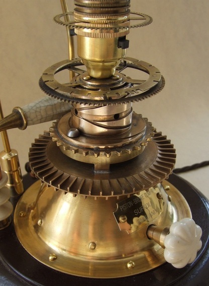
The Lamp Base
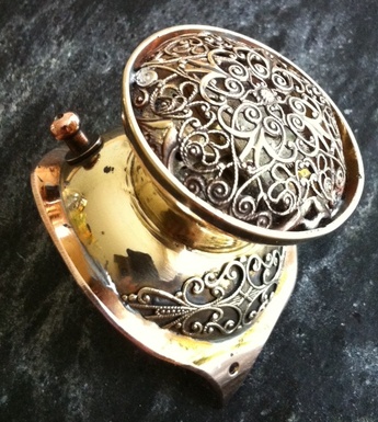
A circular wooden base was cut out and edges routed to shape. An 8mm diameter hole was drilled in the brass dome at the correct height for the switch. Additional
holes were drilled for decorative brass rivets at intervals around the dome. An 8mm hole was drilled at the top of the dome and a 6mm diameter hole at the back for the electrical cord. The 6mm hole was shimmed to protect the braided flex.
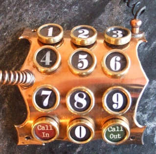
The rest of the lamp ‘stack’ was brazed together using a brass gas burner ring
fitment and two mysterious, but nonetheless interesting parts. Holes were drilled in the flange of the dome to accept the fixing screws which will eventually secure the lamp to its base. The maker’s name plaque was then riveted to the dome above the hole for the switch. I had initially intended to have the
ceramic knob at the front control a dimmer switch, sadly however, I could not find a suitable 3-core in-line dimmer that it could be connected to.
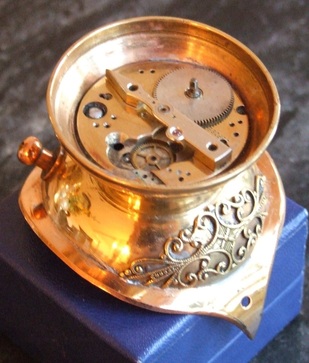
The screw-in base of the bulb holder was riveted to the centre of a large clock gear
and this, then soldered to the top of the ‘stacked’ components. This completed the metal section of the lamp base.
A circular wooden base was cut out and edges routed to shape. An 8mm diameter hole was drilled in the brass dome at the correct height for the switch. Additional
holes were drilled for decorative brass rivets at intervals around the dome. An 8mm hole was drilled at the top of the dome and a 6mm diameter hole at the back for the electrical cord. The 6mm hole was shimmed to protect the braided flex.
The rest of the lamp ‘stack’ was brazed together using a brass gas burner ring
fitment and two mysterious, but nonetheless interesting parts. Holes were drilled in the flange of the dome to accept the fixing screws which will eventually secure the lamp to its base. The maker’s name plaque was then riveted to the dome above the hole for the switch. I had initially intended to have the
ceramic knob at the front control a dimmer switch, sadly however, I could not find a suitable 3-core in-line dimmer that it could be connected to.
The screw-in base of the bulb holder was riveted to the centre of a large clock gear
and this, then soldered to the top of the ‘stacked’ components. This completed the metal section of the lamp base.
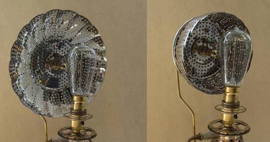
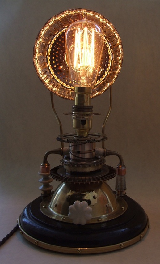
The Reflector Dish
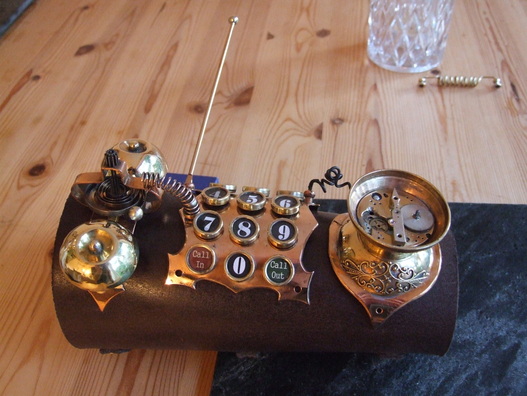
The reflector dish was made using two 12” lengths of 3/16” stock brass rod, the base of a (for want of a better description) ‘Wee-Willy Winky’ type candle holder, a stainless steel collapsible vegetable steamer and three brass curtain pull plus a few small components. I intended for the lamp shade to be reminiscent of the revolving disc seen on the back of the machine in the 1959 movie version of H G Wells’ ‘The Time Machine’.
The vegetable steamer is fully adjustable and provides a highly polished internal surface to reflect the light as well as allowing some light to pass through the small holes onto any wall behind the lamp, creating a nice secondary effect. The candle holder base fitted very snugly into the recessed rear face of the steamer and is held in place by an 8mm threaded rod with a domed cap-nut. The central focus was made from one of the three brass curtain/light pulls (same type as used at the foot of the shade supports) soldered to a brass nut, which I had to make, drill and tap with an M8 thread. Once I was happy with the fit, it was all disassembled for the two supports to be attached.
The 3/16” rod was bent to the correct shape, and one end hammered flat and shaped with the power-file to fit the curved candle holder base and then drilled. – These were riveted to the candle holder. Once this was complete the whole shade assembly could rebuilt. Two 3/16” holes were drilled into the wooden base, curtain pulls were drilled and fitted to the brass uprights, and the entire shade assembly fixed into position on the base. The final element was to create an additional base decoration reminiscent of a ‘Dr. Frankenstein’s laboratory’ type early electrical component using some ceramic insulators, copper end caps, parts from old brass extinguishers and the modern drawer handle. Once complete, the whole thing could be wired-up and all sub-assemblies fixed to the base. The final touch was to apply a brass trip around the base and apply baize
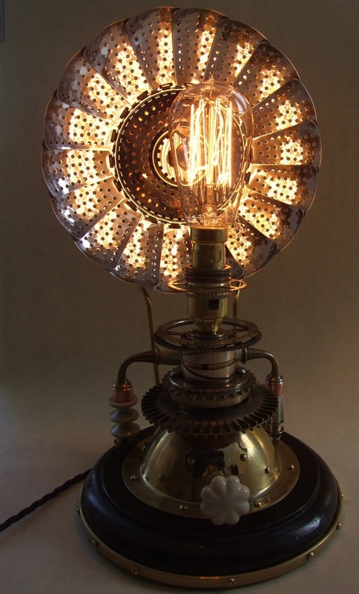
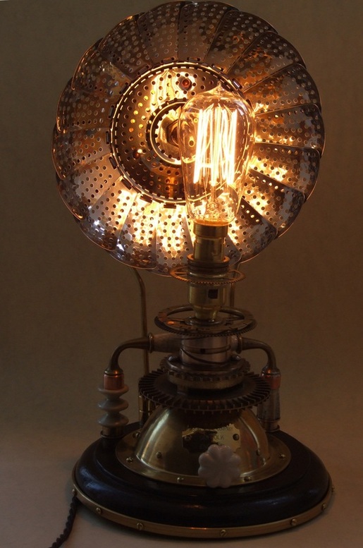
to the underside of the base. Here are some photos of it lit with the reflector in different postitions..
The reflector dish was made using two 12” lengths of 3/16” stock brass rod, the base of a (for want of a better description) ‘Wee-Willy Winky’ type candle holder, a stainless steel collapsible vegetable steamer and three brass curtain pull plus a few small components. I intended for the lamp shade to be reminiscent of the revolving disc seen on the back of the machine in the 1959 movie version of H G Wells’ ‘The Time Machine’.
The vegetable steamer is fully adjustable and provides a highly polished internal surface to reflect the light as well as allowing some light to pass through the small holes onto any wall behind the lamp, creating a nice secondary effect. The candle holder base fitted very snugly into the recessed rear face of the steamer and is held in place by an 8mm threaded rod with a domed cap-nut. The central focus was made from one of the three brass curtain/light pulls (same type as used at the foot of the shade supports) soldered to a brass nut, which I had to make, drill and tap with an M8 thread. Once I was happy with the fit, it was all disassembled for the two supports to be attached.
The 3/16” rod was bent to the correct shape, and one end hammered flat and shaped with the power-file to fit the curved candle holder base and then drilled. – These were riveted to the candle holder. Once this was complete the whole shade assembly could rebuilt. Two 3/16” holes were drilled into the wooden base, curtain pulls were drilled and fitted to the brass uprights, and the entire shade assembly fixed into position on the base. The final element was to create an additional base decoration reminiscent of a ‘Dr. Frankenstein’s laboratory’ type early electrical component using some ceramic insulators, copper end caps, parts from old brass extinguishers and the modern drawer handle. Once complete, the whole thing could be wired-up and all sub-assemblies fixed to the base. The final touch was to apply a brass trip around the base and apply baize
to the underside of the base. Here are some photos of it lit with the reflector in different postitions..
 RSS Feed
