Arty Piston-Broke - Artisan
  • Home
  • Portfolio
  • Enquiries
  • Blog
  • For Sale
  • Steampunk Medals for Sale
  • Events and Exhibitions

Optilux Desk Lamp

31/1/2014

1 Comment

 
Picture
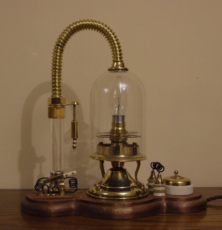
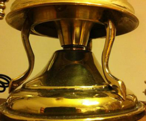
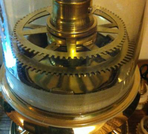
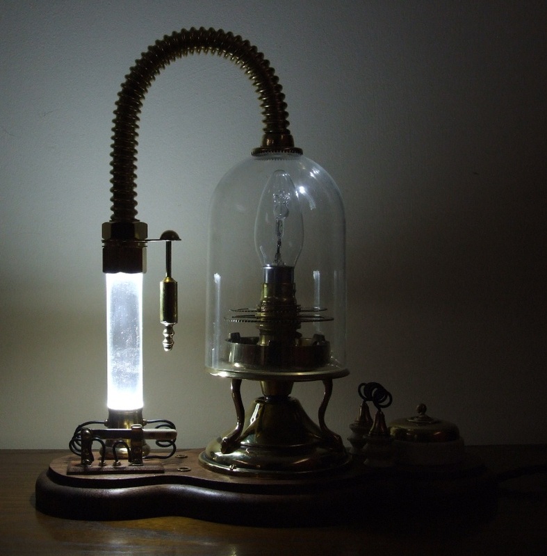
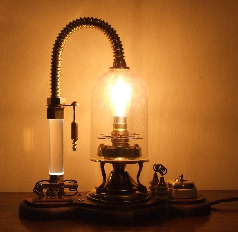
The starting point for this build was a left over glass dome and a brass base from previous projects.  The brass base is from an electric candle light, which, when inverted, fitted the diameter of the glass dome’s aperture perfectly. This sits upon a small circular three-legged candle stand, which in turn is fitted on top of a brass conical section of an old brass chandelier. Inside the candle light base, I fitted an inverted wax-catcher from another candle stick which, into which the brass bulb holder was fitted. Two large brass clock chime gears had their centres removed and were stacked between the bulb holders’ securing rings. When the lamp is lit, they cast a wonderful shadow pattern.
Picture
Picture
A wooden base was drawn out to accommodate all the parts and cut to shape and routed before being sanded and waxed to a soft sheen.

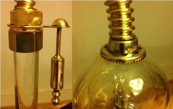
The secondary light assembly (which is on a separate low voltage battery powered circuit) is made using the clear acrylic stem of the candle light. The base of which is soldered onto a separate old brass candle shade support which is snugly fitted into a 2.5cm hole in the wooden base. The top section of the assembly utilises two securing nuts, and a lens bracket from an old pair of brass binoculars. The small assembly it supports is made from 5 brass components soldered together into a small sub-assembly. A short length of ‘Techniflex’ brass gas hose is then connected to a flanged Meccano contrate gear wheel.
Picture
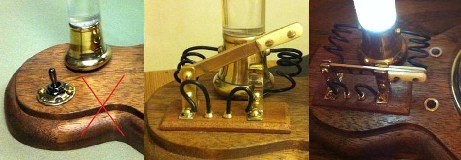
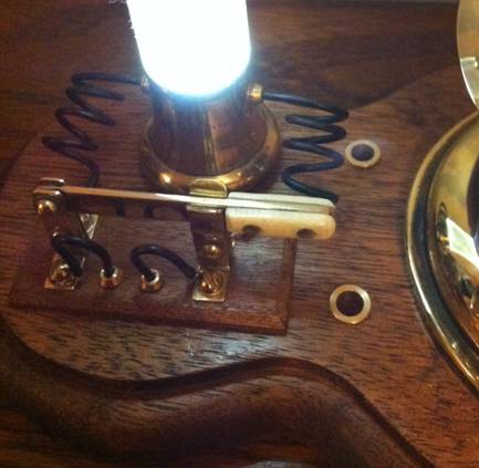
The internal lighting is provided by a laser-bright white LED powered by a concealed battery pack fitted into a routed recess in the underside of the wooden base. I wasn’t entirely happy with the first toggle switch I originally installed, (see below) so I scratch-built a bone-handled brass knife switch (made in exactly the same way as a normal riveted knife grip) and mounted it on top of the wooden base and routed the wiring using brass pipe nipples both on the switch base and the base of the light tube ‘tower’

Picture
Picture
Picture
Picture
Picture
1 Comment

Steampunk Judge Dredd 'Lawgiver' and Smoke Grenade - Commissioned order.

12/1/2014

1 Comment

 
Picture
This commission build came with very detailed  sketches and Photoshop designs from
the client making the build so much easier,  allowing for a speedy collation of
parts and assembly. The basis of the weapon is a Steampunk version  of the Lawgiver sidearm from the Judge Dredd graphic novels and comics  rather than from the more recent movie adaptations. The starting base of the  build is a plastic automatic pistol
toy. This was re-painted and, as the grips  were moulded-in to the toy, they were painted with a wood grain-effect to make  them look as if they were  screwed-on separately from the body of the pistol.  This was all done using simple acrylic paints. Once fully dried, the paint was  burnished to a soft silky sheen. Two small brass gears were applied as  decoration in the circular recesses moulded into the grip plates.
Picture
The gun was then shaped to receive the brass  barrel section. I had to remove quite a large section of the plastic barrel to  accommodate the brass parts. A power file was used for this job as it removes  plastic in seconds! 
The brass muzzle/barrel assembly is made up of  four main components. A 33mm
diameter brass tube with a screw-top obtained from  an old grease syringe, which had to be marked out and drilled with over 100  evenly-spaced vent holes! The barrel itself is simply a short length of 12mm  diameter brass tube soldered to the cap of the syringe. The conical terminal of  the barrel was made from the plunger grip part of an old fire extinguisher – I  have many of these parts in the workshop but never found a suitable use for them  until now! I had to remove the two lugs and drill out the barrel before  soldering it to the 12mm tube.
Picture
The barrel sub-assembly is fixed to the  pistol by two M4 bolts passing through the gun and into the brass venting tube.  I had to drill and tap two matching M4 threaded holes for this. A small shaped  brass plate was made and screwed on to the gun to help hold the two halves of  the plastic gun together. Small self-tapping screws were used.
Picture
Next, was the screw-dial at the rear of the  gun. The original comic book art shows this as a fluted cylindrical component,  but to give the build a more ‘Victorian’ feel, I took the liberty of utilising  an antique brass sword pommel and part of a small candlestick for a more  decorative ‘period’ look. These parts were soldered to a small brass plate which was pre-cut  and made convex to fit the curved surface at the rear of the gun. Five small  self-tapping screws hold  this sub-assembly to the main body of the  gun.
Picture
The next step was the magazine section.  Using a ‘U’ shaped wooden core, recessed to fit the underside of the pistol,  metal side plates were cut to shape, drilled and fixed to the wood core.  Additional brass plates and drive gears were riveted on. The cartridge cases visible  through the side of the magazine are simply four short lengths of 15mm copper  pipe. Once the magazine was completed, it was fixed to the pistol using two  lengths of M4 threaded rod and brass domed cap nuts.
Picture
The most complicated part of the build was the  dial section. The client kindly provided a detailed graphic of the dial plate  itself which was most helpful! Once printed out to the correct size, the casing  of the dial could be constructed. Firstly, two semi-circular brass plates were  cut from sheet brass. One for the blank inside plate and the other cut with an  aperture for the front of the dial glass. 
 
4mm copper edging tube was cut to length, bent  to the correct radius and then split
along the length of the internal radius  using a Dremel cutting disc, so that it could be fitted and soldered into place  on to each of the end plates. The rear/inner plate was covered in thin antiqued  goat leather before the edging was applied. Once the edging was in place, a  central brass strip was cut and soldered into position onto the front dial plate  only. A small filigree decoration was then soldered across the top of the arch.  A movable copper pointer arm was then riveted to the dial plate. The dial  graphic and clear acrylic ‘glass’ could them be shaped, drilled and riveted into  place. Lastly, the leather-covered side plate could be soldered into  place.
Picture
Some shaping of the ends of the arch strip was  then required to make it a matched fit over the contours of the pistol body and  barrel assembly. Once completed, the dial assembly was bolted to the pistol  using another two lengths of M4 threaded rod and brass domed cap nuts as used  for the magazine section.

The final details to add were to make and apply the small amount of copper and brass pipe work to the outer face of the gun and then  any visible screw holes on the plastic gun were covered using brass rivet caps.
Picture
Picture
Picture
Picture
The grenade was made using parts from an old  40mm diameter brass garden sprayer, a
brass pipe reducer and some custom-built  parts. As the base uses a garden sprayer, the first thing to do was solder a  thin brass disc over the sprayer holes (now the base cap of the grenade). The  cap was made by using the pump end of the sprayer fitted with a brass pipe  reducer. A slot was then cut into the top of the reducer to receive the pin-lock  and hinge pin assembly. At this stage, the grooves were cut and holes drilled into the cylinder

The hinge pin assembly is simply two short  lengths of 12mm x 2mm brass bar stock
soldered together, shaped and drilled at  each end. One hole for the hinge pin, the other for the grenade’s release pin.  The hinge pin is 3.2mm (1/8”) brass rod. Once soldered into position, this left  the release arm to complete. The release arm was made from 2.5mm brass  plate, shaped and formed into the correct bends. A ‘Π’ shaped section was then soldered inside the  arm  and drilled to accommodate the release pin. The pin itself is a 3.2mm brass  rod hammered flat at one end and drilled to take the 2.0mm wire ring.
Picture
Picture
Picture
1 Comment

    Author

    Having recently been absorbed into the world of Steampunk, I will attempt to show here some of my work-in-progress as projects develop.

    Archives

    June 2015
    May 2015
    January 2015
    September 2014
    January 2014
    November 2013
    September 2013
    August 2013
    July 2013

    Categories

    All

    RSS Feed

Powered by Create your own unique website with customizable templates.