
This commission build came with very detailed sketches and Photoshop designs from
the client making the build so much easier, allowing for a speedy collation of
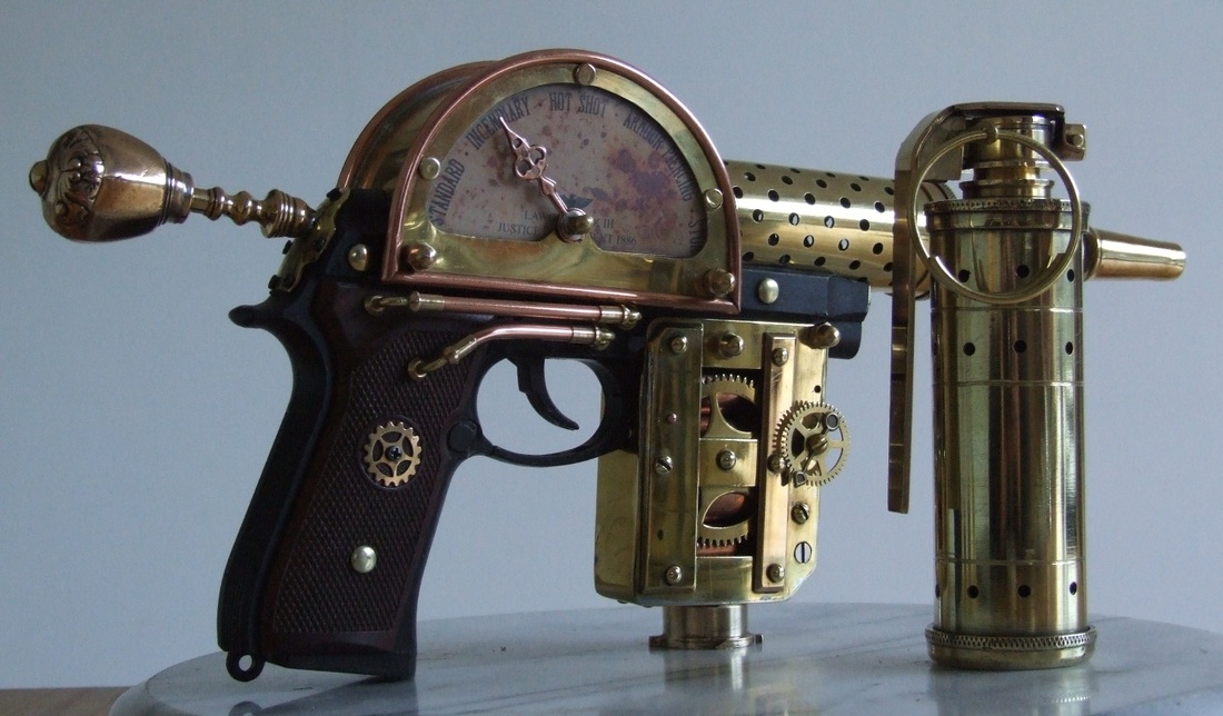
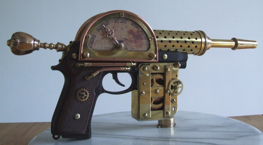
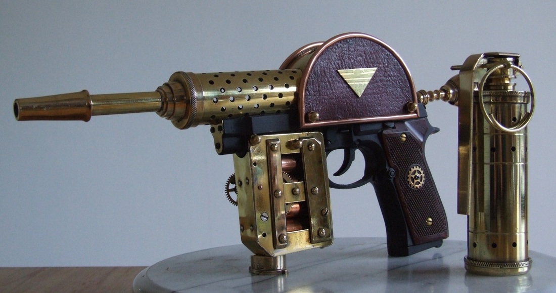
parts and assembly. The basis of the weapon is a Steampunk version of the Lawgiver sidearm from the Judge Dredd graphic novels and comics rather than from the more recent movie adaptations. The starting base of the build is a plastic automatic pistol
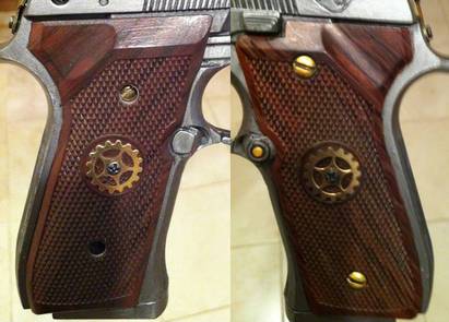
toy. This was re-painted and, as the grips were moulded-in to the toy, they were painted with a wood grain-effect to make them look as if they were screwed-on separately from the body of the pistol. This was all done using simple acrylic paints. Once fully dried, the paint was burnished to a soft silky sheen. Two small brass gears were applied as decoration in the circular recesses moulded into the grip plates.
the client making the build so much easier, allowing for a speedy collation of
parts and assembly. The basis of the weapon is a Steampunk version of the Lawgiver sidearm from the Judge Dredd graphic novels and comics rather than from the more recent movie adaptations. The starting base of the build is a plastic automatic pistol
toy. This was re-painted and, as the grips were moulded-in to the toy, they were painted with a wood grain-effect to make them look as if they were screwed-on separately from the body of the pistol. This was all done using simple acrylic paints. Once fully dried, the paint was burnished to a soft silky sheen. Two small brass gears were applied as decoration in the circular recesses moulded into the grip plates.
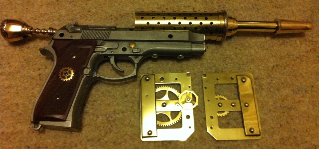
The gun was then shaped to receive the brass barrel section. I had to remove quite a large section of the plastic barrel to accommodate the brass parts. A power file was used for this job as it removes plastic in seconds!
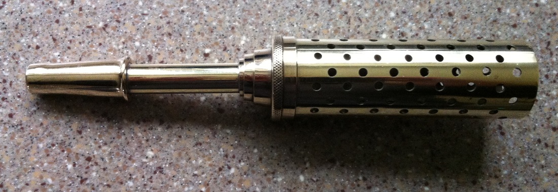
The brass muzzle/barrel assembly is made up of four main components. A 33mm
diameter brass tube with a screw-top obtained from an old grease syringe, which had to be marked out and drilled with over 100 evenly-spaced vent holes! The barrel itself is simply a short length of 12mm diameter brass tube soldered to the cap of the syringe. The conical terminal of the barrel was made from the plunger grip part of an old fire extinguisher – I have many of these parts in the workshop but never found a suitable use for them until now! I had to remove the two lugs and drill out the barrel before soldering it to the 12mm tube.
The barrel sub-assembly is fixed to the pistol by two M4 bolts passing through the gun and into the brass venting tube. I had to drill and tap two matching M4 threaded holes for this. A small shaped brass plate was made and screwed on to the gun to help hold the two halves of the plastic gun together. Small self-tapping screws were used.
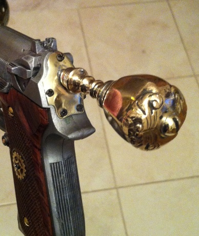
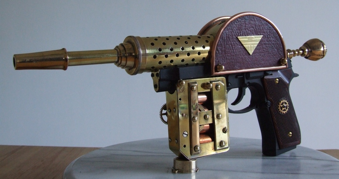
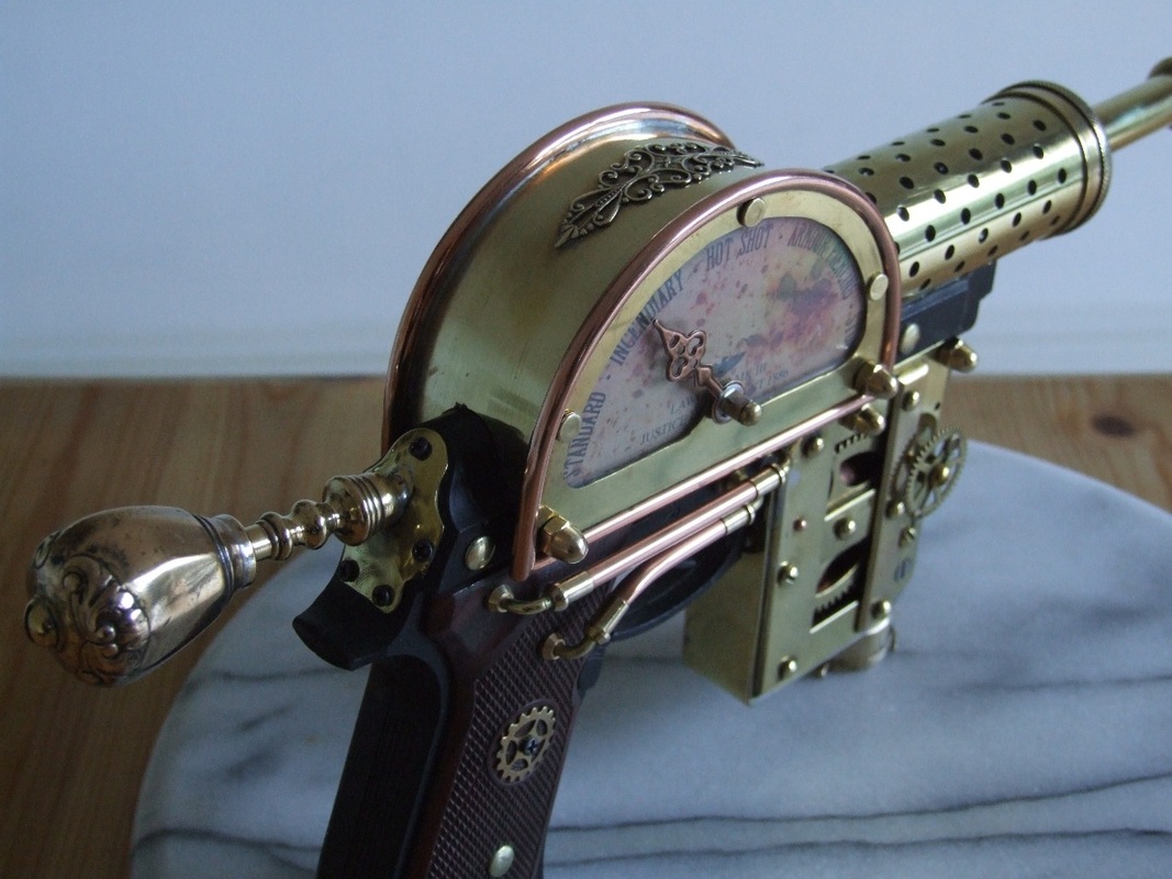
Next, was the screw-dial at the rear of the gun. The original comic book art shows this as a fluted cylindrical component, but to give the build a more ‘Victorian’ feel, I took the liberty of utilising an antique brass sword pommel and part of a small candlestick for a more decorative ‘period’ look. These parts were soldered to a small brass plate which was pre-cut and made convex to fit the curved surface at the rear of the gun. Five small self-tapping screws hold this sub-assembly to the main body of the gun.
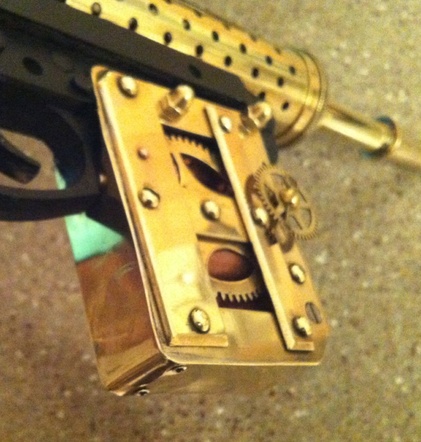
The next step was the magazine section. Using a ‘U’ shaped wooden core, recessed to fit the underside of the pistol, metal side plates were cut to shape, drilled and fixed to the wood core. Additional brass plates and drive gears were riveted on. The cartridge cases visible through the side of the magazine are simply four short lengths of 15mm copper pipe. Once the magazine was completed, it was fixed to the pistol using two lengths of M4 threaded rod and brass domed cap nuts.
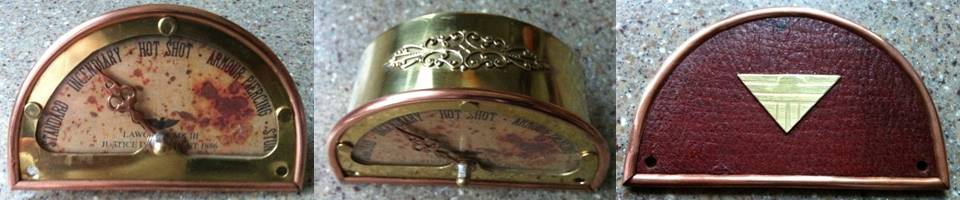
The most complicated part of the build was the dial section. The client kindly provided a detailed graphic of the dial plate itself which was most helpful! Once printed out to the correct size, the casing of the dial could be constructed. Firstly, two semi-circular brass plates were cut from sheet brass. One for the blank inside plate and the other cut with an aperture for the front of the dial glass.
4mm copper edging tube was cut to length, bent to the correct radius and then split
along the length of the internal radius using a Dremel cutting disc, so that it could be fitted and soldered into place on to each of the end plates. The rear/inner plate was covered in thin antiqued goat leather before the edging was applied. Once the edging was in place, a central brass strip was cut and soldered into position onto the front dial plate only. A small filigree decoration was then soldered across the top of the arch. A movable copper pointer arm was then riveted to the dial plate. The dial graphic and clear acrylic ‘glass’ could them be shaped, drilled and riveted into place. Lastly, the leather-covered side plate could be soldered into place.
Some shaping of the ends of the arch strip was then required to make it a matched fit over the contours of the pistol body and barrel assembly. Once completed, the dial assembly was bolted to the pistol using another two lengths of M4 threaded rod and brass domed cap nuts as used for the magazine section.
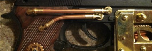
The final details to add were to make and apply the small amount of copper and brass pipe work to the outer face of the gun and then any visible screw holes on the plastic gun were covered using brass rivet caps.
The final details to add were to make and apply the small amount of copper and brass pipe work to the outer face of the gun and then any visible screw holes on the plastic gun were covered using brass rivet caps.
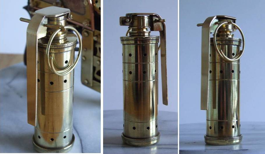
The grenade was made using parts from an old 40mm diameter brass garden sprayer, a
brass pipe reducer and some custom-built parts. As the base uses a garden sprayer, the first thing to do was solder a thin brass disc over the sprayer holes (now the base cap of the grenade). The cap was made by using the pump end of the sprayer fitted with a brass pipe reducer. A slot was then cut into the top of the reducer to receive the pin-lock and hinge pin assembly. At this stage, the grooves were cut and holes drilled into the cylinder
The hinge pin assembly is simply two short lengths of 12mm x 2mm brass bar stock
soldered together, shaped and drilled at each end. One hole for the hinge pin, the other for the grenade’s release pin. The hinge pin is 3.2mm (1/8”) brass rod. Once soldered into position, this left the release arm to complete. The release arm was made from 2.5mm brass plate, shaped and formed into the correct bends. A ‘Π’ shaped section was then soldered inside the arm and drilled to accommodate the release pin. The pin itself is a 3.2mm brass rod hammered flat at one end and drilled to take the 2.0mm wire ring.

 RSS Feed
