This build was inspired by the fantastic clockwork ‘Thing’ made by Dr. A. His use of the artists hand model was used to great effect.
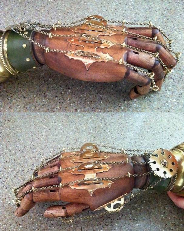
The Hands.
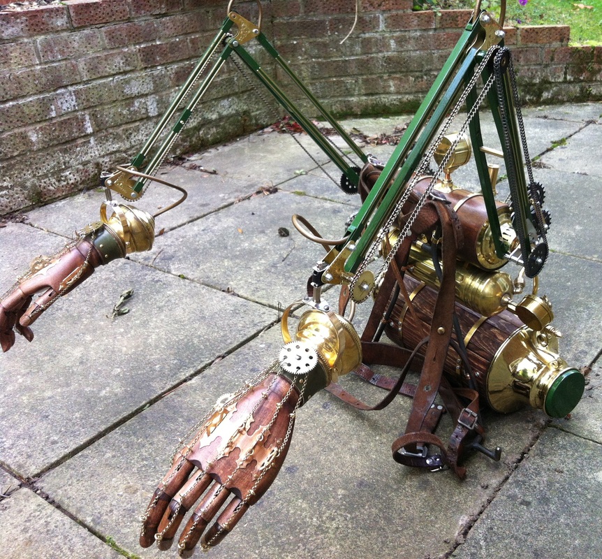
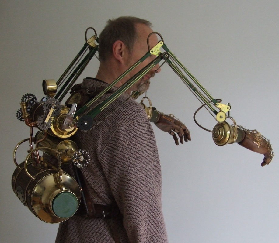
Finding a pair was a difficulty in itself! After lightly sanding the hands, they were given a few cloth-applied layers of wood stain to achieve the desired effect. The wrist sections were sawn shorter in order that they fitted into the two brass bedknobs I had set aside for the terminals. Each bedknob was drilled and an eyelet soldered into place for the power cable routing. The wooden hands are temporarily secured into the recesses of the bedknobs with two screws before a small strip of green leather was applied with contact adhesive and secured with brass rivets. Once assembled, a bronze plate was cut to shape and formed for the back of each hand (four fingers) and a smaller similar plate for the thumbs. Into the cut slots I soldered old half clock gears. These would be for attaching the chains to operate the digits. Once the bronze plates were nailed into position, the chains were attached and run through screw-in eyelets and secured at each finger and thumb tip. A flat brass bar was cut and shaped for the gimble suspension and fixed to the bedknob.
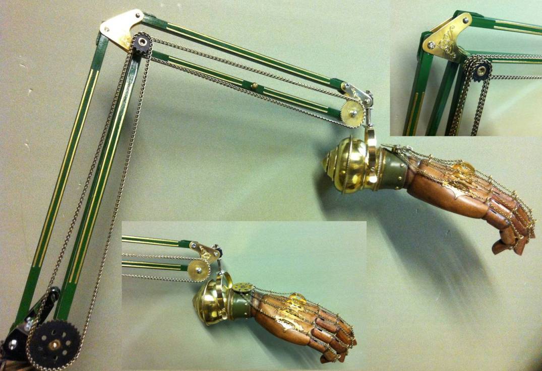
The Arms.
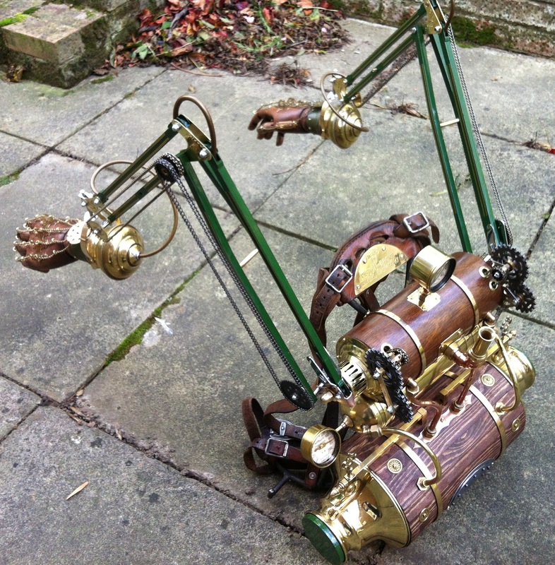
This was a relatively easy section to complete. The arms are simply anglepoise lamp arms – a cheap pair from a well known DIY supplier. They came fitted with chrome hinge plates which I replaced by cutting new brass ones. The bases, shades and springs were also removed and the arm sections re-painted. The chain drive was made using Meccano gears and drive chain. The hands are fixed to the shade holder with rivets.
I kept the original steel fittings in place for the attachment to the backpack axle as they are stronger that brass ones would be. These were drilled at a slight offset and the holes filed hexagonal to fit onto the 10mm brass hexagonal section axle.
The Backpack
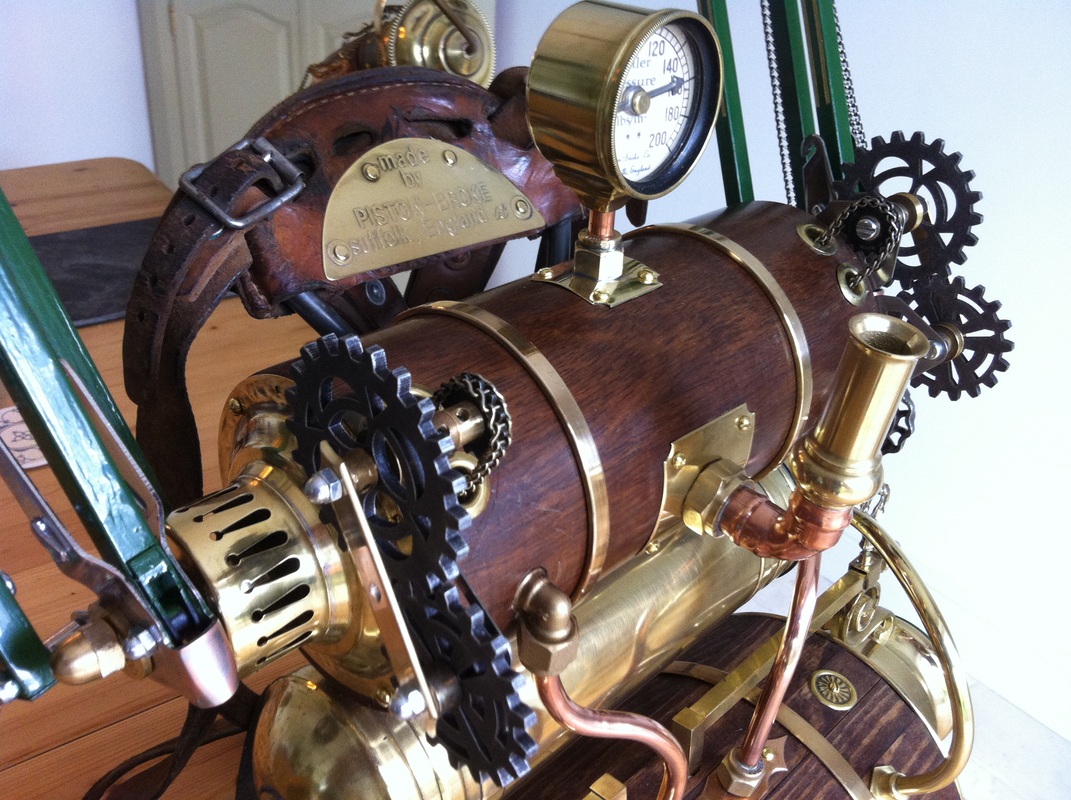
The frame used to support the sub-assemblies of the backpack is from an old military rucksack. The frame is strong steel and very comfortable to wear even with the weight of the entire build attached. I kept the original leathering as it had an nice aged look about it. The only addition was the maker’s name plaque that I etched and riveted to the curved section at the top of the frame.
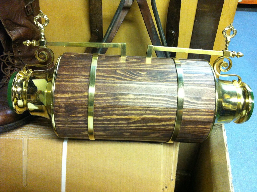
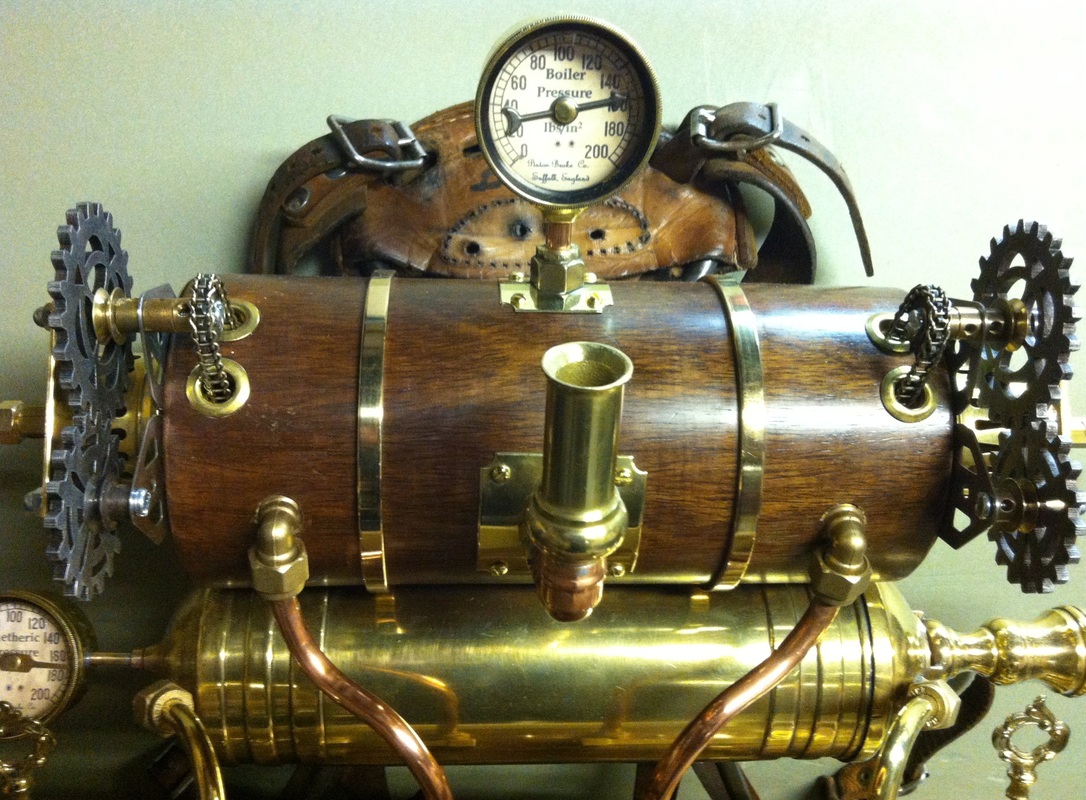
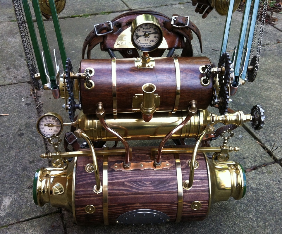
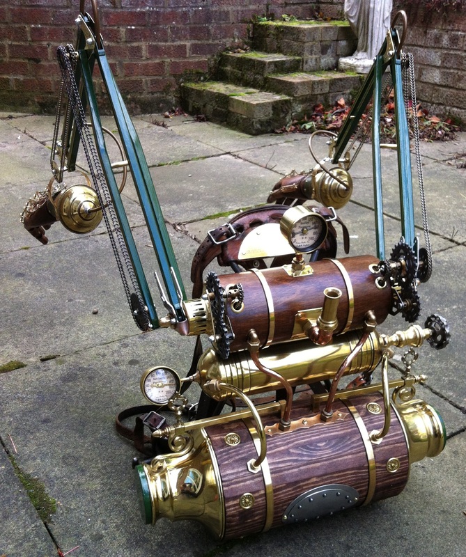
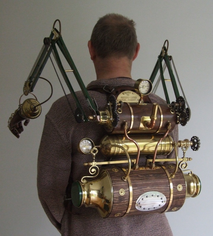
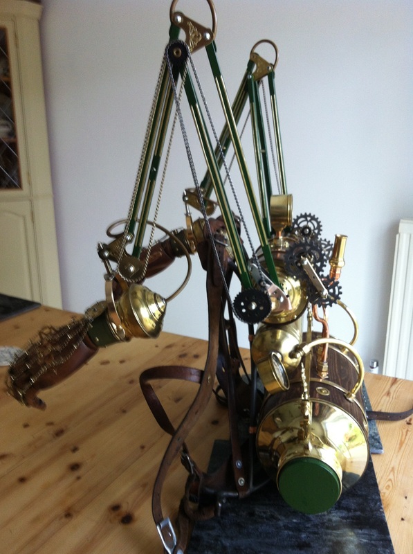
I started with the (lower) boiler assembly. The core of which is a large diameter card postal tube cut to length. The brass ends are made from a pair of lamp shades capped with two painted lids. Wooden slats were cut to length and applied to the card core. Once in place, they were given a liberal staining to achieve the dark colouring. Two brass strips were formed and attached to fully secure the slats in place. Holes were drilled for the shade bracket attachments which are secured by hex nuts on the inside of the tube. Decorative rosettes were screwed onto the wood and four brackets hold the entire sub-assembly securely to the frame.
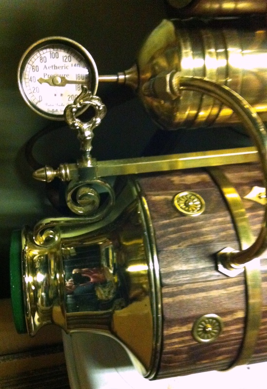
The next (middle) pressure vessel section utilises a brass fire extinguisher body. The extinguisher was opened and all internals were removed to reduce the weight considerably (some of the parts are cast in lead!) A section of candlestick and a wheel valve were then fitted to one end and a gauge fitted to the opposite end. The two gauges used on the build were made using tube and lens parts from an old pair of binoculars. A backing plate was soldered to the back and a customised (Piston-Broke) printed dial and indicator inserted. The sub-assembly is then fitted to the frame with brackets. To strengthen and augment the support of the brass cylinder on the frame, two brass pipes (also parts of the two lamps) were shaped and fitted between the two sections.
The upper ‘drive’ section started out as a turned wooden cylindrical vase cut to length. Brass end-caps were made using brass lampshade parts. The vented portions are from the pair of lamps used in the lower section. These were drilled and the holes filed hexagonal to receive the axle bar. Holes were then made for the drive chains and edged in brass using eyelets. The small flue section was made from a section of candle stick and plumbing parts fixed to the cylinder on a curved brass backing plate (as was the gauge at the top of this section).
The gear mechanisms were assembled using Meccano and MDF gears trains made by the excellent people at Cog’o’Two http://www.cogotwo.com/ which I painted to resemble burnished iron castings. The drive chains are long enough to encircle the brass axle running through the assembly. Once secured by brackets to the frame, copper pipes were then shaped and fitted to provide added support by connection to a bronze plate to the lower boiler section. Lastly, the 10mm hexagonal section axle was given an 8mm threaded end and inserted through the drive section and soldered in-place at each end.
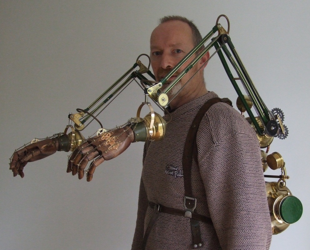
The arms are attached to the axle and secured by brass domed cap nuts. The entire assembly is surprisingly light and comfortable to wear thanks to the design of the rucksack frame. The weight of the arms acts as a counter-balance for the weight of the backpack section! Here's a few more shots of the completed build..

 RSS Feed
